Calibration Repairs
46 Product Manual IRB 640
6. Align the pin and tool with a sliding calliper. See Figure 9.
Figure 9 Aligning the pin and tool with a sliding calliper for axis 1.
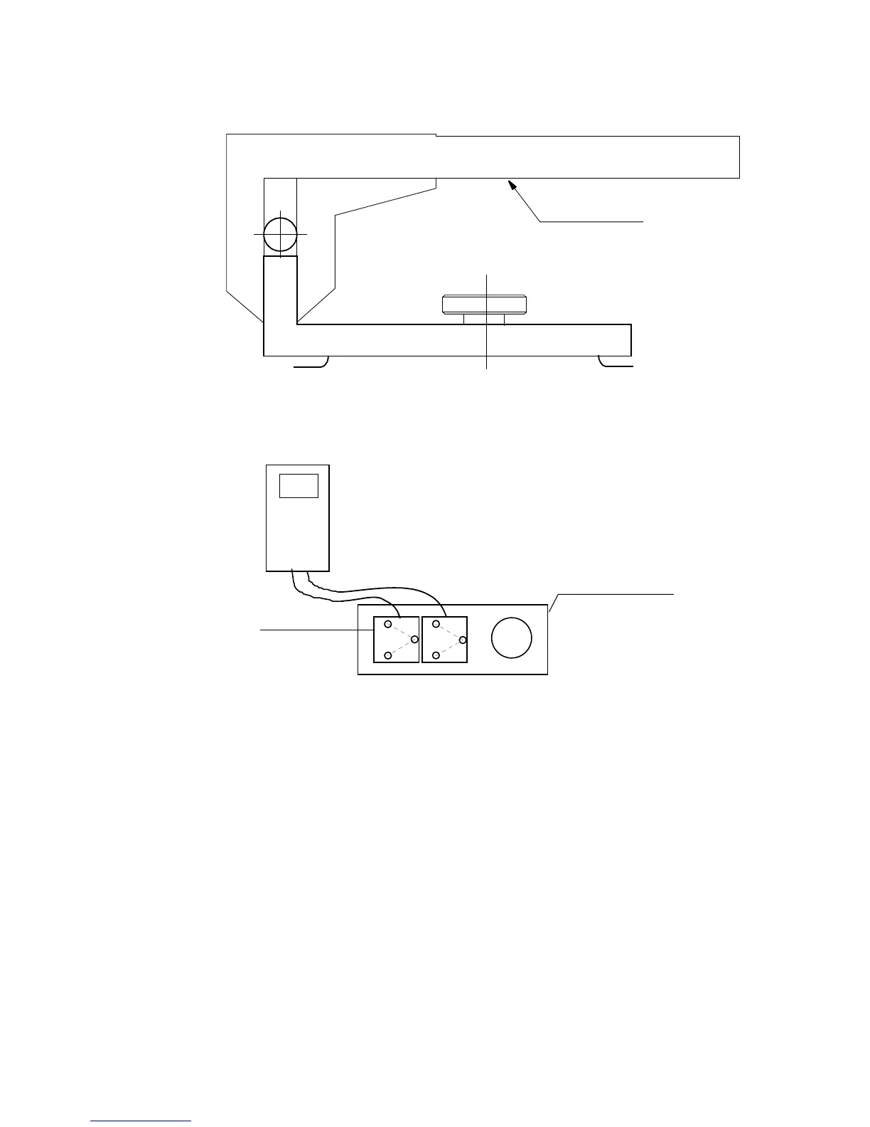
Before calibrating axes 2, 3 and 6, calibrate the sensors against each other, using a reference
plane surface, in the same direction. See Figure 10.
Figure 10 Calibrating the sensors.
Axes 2, 3 and 6
7. Release the enabling device.
8. Mount sensor fixture 6808 0011-GM on the base’s reference plane, see Figure 11.
9. Mount elbow fixture 6808 0011-LP on the lower arm’s calibration plane, see Figure 11.
10. Mount sensor fixture 6808 0011-GM at the back of the upper arm, see Figure 11.
11. Mount sync fixture 3HAC 1904-1 on the frame for axis 6 and turning disc,
see Figure 12.
12. Mount inclination instrument 6807 081-D. One sensor should be mounted on the refer-
ence plane and the other on the elbow fixture for axis 2. Both sensors should be posi-
tioned in the same direction. See also Figure 11.
Note that the sensor unit must always be mounted on top of the fixture.
MANIPULATOR
6896 0011-YM
Sliding calliper
0000
Reference plane
Sensor