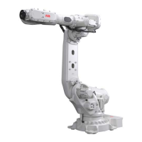
Do you have a question about the ABB IRB 640 and is the answer not in the manual?
Instructions for safely lifting the robot manipulator, including required equipment and procedures.
Detailed steps for assembling the robot manipulator onto its mounting surface.
Procedure for manually engaging and disengaging the robot's axis brakes.
Schedule outlining prescribed maintenance tasks and intervals for the manipulator.
General instructions and procedures for performing maintenance on the robot.
Procedure for replacing the battery in the robot's measuring system.
Important safety cautions regarding lifting heavy parts and switching off power.
Step-by-step instructions for dismounting and mounting the motor for Axis 1.
Instructions for dismounting and mounting the gearbox for Axis 2.
Detailed steps for dismounting and mounting the lower arm of the robot.
Detailed steps for dismounting and mounting the motor for Axis 3.
Instructions for dismounting and mounting the gearbox for Axis 3.
Detailed instructions for dismounting and mounting the complete upper arm.
Detailed steps for replacing the upper and lower rods of the robot's link system.
Detailed steps for dismounting and mounting the tilt housing for Axis 6.
Instructions for replacing the motor and gearbox assembly for Axis 6.
Overview of the robot measurement system and conditions requiring calibration.
Step-by-step guide for calibrating robot axes 1, 2, 3, 5, and 6.
Procedure for updating revolution counters using calibration marks on the manipulator.
Methods for verifying the robot's calibration position using diskette or jogging.
Circuit diagram for the robot's brake unit.
Circuit diagram for Axis 1, showing its electrical connections.
Circuit diagram for Axis 2, showing its electrical connections.
Circuit diagram for Axis 3, showing its electrical connections.
Circuit diagram for Axis 6, showing its electrical connections.


