5
1 Introduction
This manual is designed to provide information on installing,
operating and troubleshooting the LMT Series of level
transmitters. This LMT Series is comprised of the LMT100 and
LMT200 models.
Every section of this manual is dedicated to the specific phases
of the LMT lifecycle. The start of the lifecycle begins with the
receipt of the transmitter and its identification and continues
through installation, the connection of all electrical
components, the configuration of the device and finally ends
with the troubleshooting and maintenance operations.
Product description
The LMT Series of level transmitters is a modular range of field
mounted, microprocessor-based electronic transmitters,
utilizing multiple sensor technologies. Accurate and reliable
measurement of liquid levels is provided in even the most
difficult and hazardous industrial environments. The LMT
Series can be configured to provide specific industrial output
signals, according to Fieldbus digital communication. The LMT
Series consists of two models (LMT100 & LMT200):
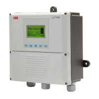
Sensor
Sensor Wire
Sensor Tube
Current
pulse
Figure 1 LMT100 (insertion-mounted)
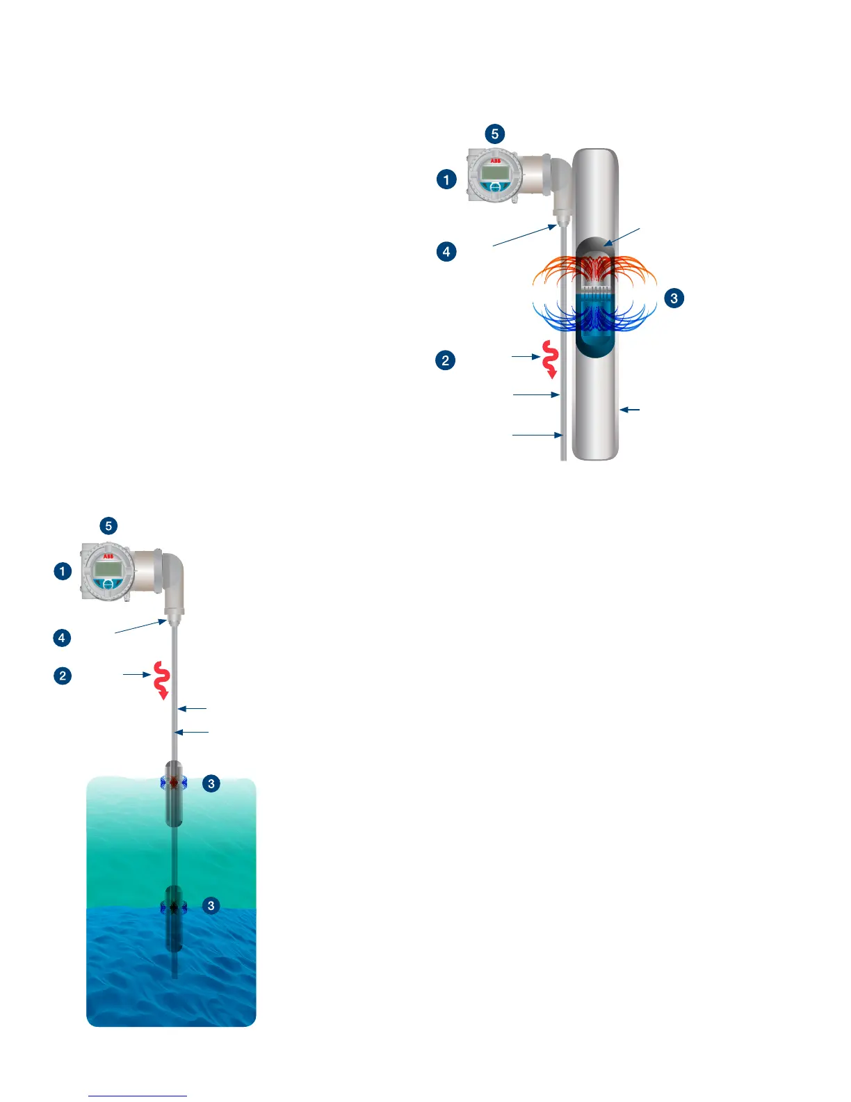
Sensor
Sensor
wire
Current
pulse
Magnetic float
assembly
Sensor
tube
Gauge (KM26)
Figure 2 LMT200 mounted on gauge (KM26)
The LMT Series is based upon the magnetostrictive principle.
1 The device electronics generates a low energy current pulse
at fixed intervals.
2 The electrical pulses create a magnetic field which travels
down a specialized wire inside the senor tube.
3 The interaction of the magnetic field around the wire and the
magnetic float causes a torsional stress wave to be induced
in the wire. This torsion propagates along the wire at a
known velocity, from the position of the magnetic float and
toward both ends of the wire.
4 A patented sensing element placed in the transmitter
assembly converts the received mechanical torsion into an
electrical return pulse.
5 The microprocessor-based electronics measures the elapsed
time between the start and return pulses (Time of Flight)
and converts it into a position measurement which is
proportional to the level of the float.