Damping
Level transmitter output signals that are noisy as a result of the
process can be smoothed (damped) electrically. Damping is a
setting designed to delay the mA output response to a change
in measured level.
Different scenarios require different damping settings:
• If the process is agitated or splashing of the liquid is possible,
a higher damping value may be required.
• If the process changes rapidly, a lower damping value may be
needed to increase the response time to a level change.
Damping can be described as the time responsiveness of the
device to the change in measured level. The relationship
between damping to changes in input can be described in the
following formula where A equals change in measurement
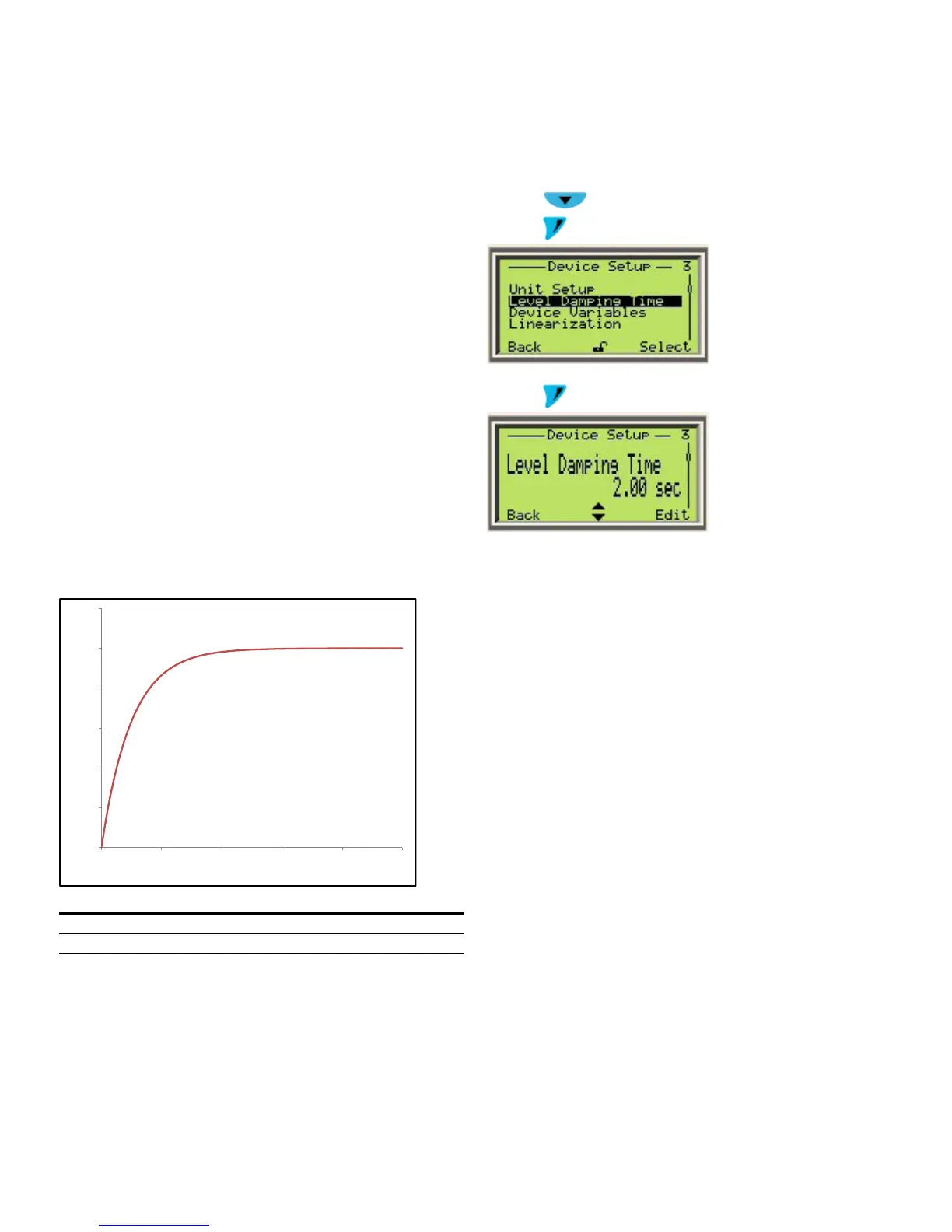
From this equation a table and graph can be derived to
illustrate the delay in reaction time due to changes in the
damping value
0
0.2
0.4
0.6
0.8
1
1.2
0 2 4 6 8 10
Fraction of amplitude change
Response time in multiples of damping input value
Time Multiplier
% of Input Value
Figure 29 Damping
The additional time constant can be set between 0.1 seconds
and 60 seconds in increments of 0.1 seconds. Damping does
not affect the value shown on the digital display as a physical
unit. Damping only affects the parameters derived from it, such
as analog output current, free-process variable, input signal for
the controller and so forth. The damping adjustment can be
performed through the HMI display or handheld terminal.
Adjusting damping settings through HMI display
1 Enter the menu: Device Setup
2 Press
to select Level Damping Time
3 Press
to confirm the selection
4 Press to edit the Level Damping Time
Overview of the linearization/strapping tables
Linearization is an approximation to a function at a given point.
The LMT has 21 linearization points available for implementing
up to 20 segments of linear calibration.
Linearization allows significant improvements of measurement
accuracy in tanks and vessels with irregular shapes. If
linearization were not used in these cases, the resulting level
calculation would not meet the expected accuracy due to the
non-linear function between the level in the tank and the
calculated level.
For effective use of the multipoint calibration using
linearization tables, it is important to understand the
advantages that it provides and the limitation of its use.
Typically, there is a need for linearization/strapping tables in
the following scenario:
• The user intends to use Volume or Flow as the Output Type.
• The tank or vessel is irregularly shaped and the function
between the level in the tank and the calculated level is non-
linear.
Practical use of linearization/strapping table
Assume that Volume will be used as the Output Type in the
tanks shown in Figure 28 below. For these tanks, only two
points need to be enabled in the linearization/strapping table.
The reason for this is that the Volume is a linear function of the
Level being measured. In both cases, the volume is equal to the
factor of the area of the base of the tank by the liquid level.