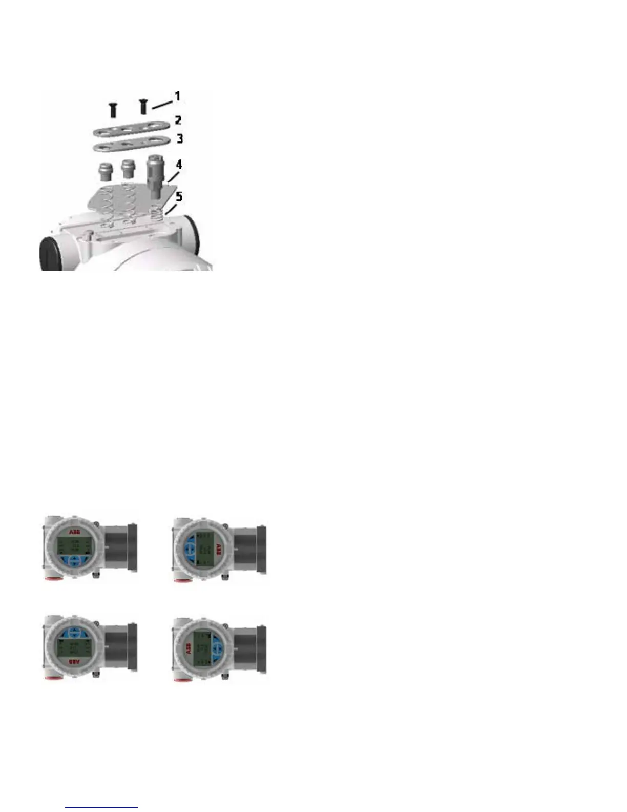
Figure 15 External push button assembly components
Installing / removing the HMI display
– Unscrew the housing cover of the communication board /
HMI side.
IMPORTANT (NOTE)
With an Ex d / flame-proof design, please refer to the securing
the housing cover in flame-proof areas section.
• Attach the HMI display. Depending on the mounting position
of the level transmitter, the HMI display may be attached in
four different positions.
• This enables + 90° or + 180° rotations (see Figure 16).
IMPORTANT (NOTE)
Retighten the housing cover until it is hand-tight.
Default 90°
180° 270°
Figure 16 Windowed front cover and HMI display
Integral display rotation
When the optional integral display meter is installed, it is
possible to mount the display in 4 different positions, rotated
clockwise or counterclockwise with 90° steps. To rotate the
display, open the windowed cover (hazardous area precautions
must be respected) and pull the display housing from the
communication board. Re-position the display connector
according to the preferred position. Push the display module
back onto the communication board.
Ensure the plastic fixing locks are in place.
Securing the housing in flame-proof areas
Each of the front faces of the electronics housing features a
locking screw (hex-head socket screw) on the bottom side.
• Install the housing cover to the housing by hand-tightening it.
• Turn the locking screw counterclockwise to secure the
housing cover. This involves unscrewing the screw until the
screw head stops at the housing cover.