5 Unscrew the communication board and gently disconnect
the connector on back of the board
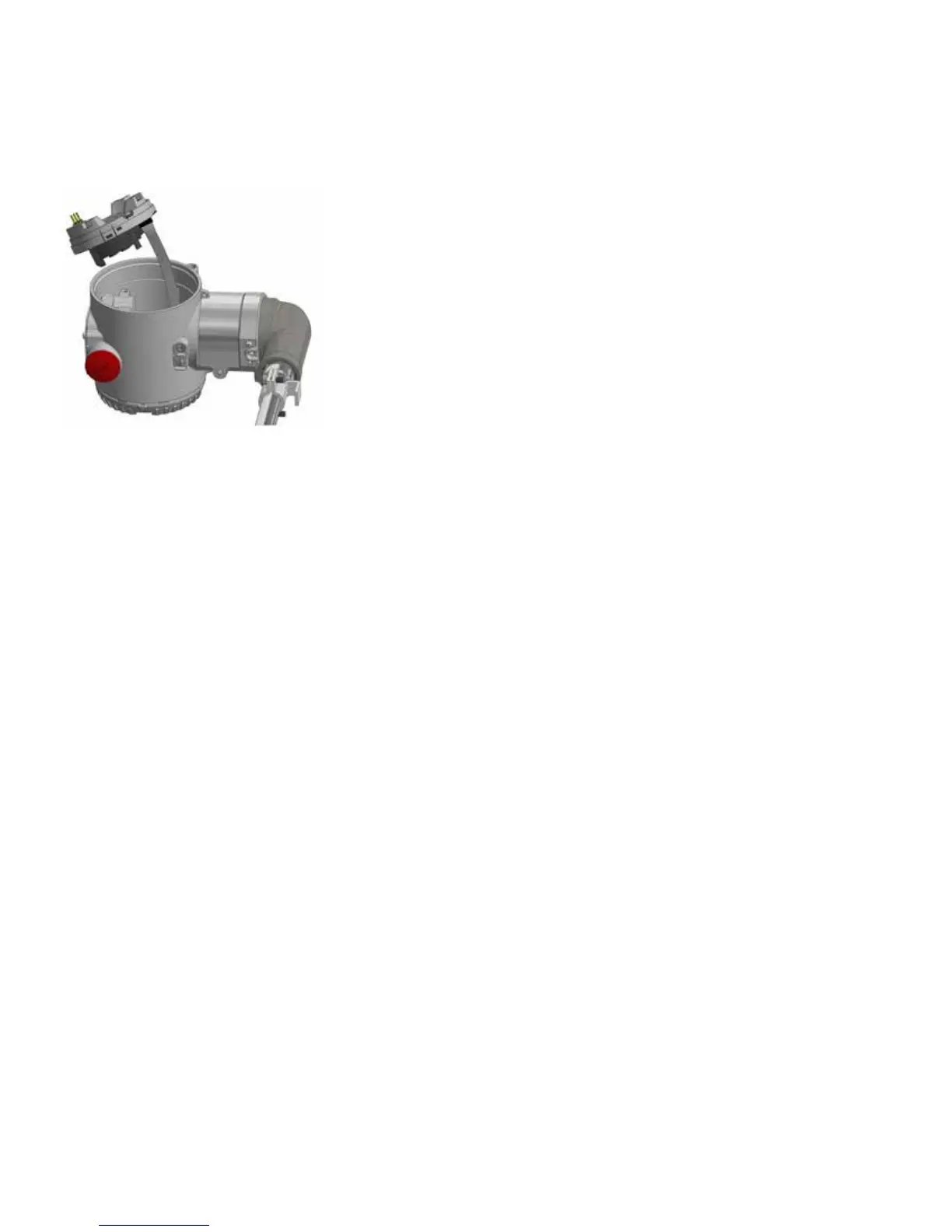
Figure 41 Communication Board
6 Connect the sensor flat cable to the new electronic module
with dip switch 1 in up position.
7 Screw the new communication into the housing.
8 Connect the transmitter to power supply, wait ten seconds
and lower dip-switch 1 to 0 position. LMT can reconfigure
itself with the previous configured parameters thanks to the
auto-configuration functionality.
9 Reset the dip switch position
10 Connect back the HMI board on top the communication
board with the double male header connector removed in
step 3.
11 Place back the window cover removed during step 2.
Safety Inspection and test
An LMT Series transmitter can be divided up into four major
components the float, the sensor, the transmitter and the
output. All of these components and their subcomponents
should be evaluated during each periodic inspection. This
inspection (and possible repair) should take less than 4 hours if
the proper tools are made available. Prior to inspection, the
transmitter should be removed from service following end user
specified procedures regarding lockout, tagout, wiring and
cleaning. Once removed from service, the LMT Series
transmitter should be laid on a flat even surface. For detailed
safety guidelines, refer to the LMT Series Safety Manual (SM
LMT100200- EN A)
Float inspection
The LMT Series will detect and report the position of the float
on its sensor tube as a level of fluid in the process. In order to
measure the fluid in the process properly, the float must move
freely up and down the sensor tube partially submerged in the
liquid level. If the float were to become damaged or stuck on
the sensor tube, the transmitter will still report the float
position regardless of the actual process fluid level. This by
definition is a Dangerous Undetectable failure. To prevent this
failure the float will need to be inspected for integrity and
movement. Some transmitters will have two floats mounted on
the sensor tube. This inspection should be done on both floats.
1 Move the float up and down the length of the sensor tube. It
should move freely from the bottom of the sensor tube to
the process connection.
2 Remove the float from the sensor tube by removing the
retaining clip or bolt from the end of the transmitter. Inspect
the float for signs of excessive wear or damage.
3 Submerge the float in a container of water to check for leaks
as air bubbles escaping from the float. The float is a sealed
unit and any holes in the shell of the float could allow process
fluid to seep inside.
IMPORTANT (NOTE)
ABB floats are designed for different specific gravity ranges.
The float may or may not float in the water. It may be necessary
to hold the float under the water to perform this test.
Upon completion of float inspection, place the float back on the
sensor tube paying careful attention to float orientation. Some
LMT Series transmitters will be equipped with float spacers
designed to keep the float positioned in the measurable range
of the sensor tube. It is important that the spacer be replaced
when the transmitter is reassembled.
IMPORTANT (NOTE)
When handling the transmitter ensure the probe does not bend
during installation. A bend in the probe could prevent the float
from travelling freely up and down and it could damage the
magnetostrictive wire fitted inside.
Sensor inspection
The sensor of the LMT Series consists of a metal tube
containing several wires. The sensor tube will measure the float
location properly if the tube is straight and the float can travel
freely up and down its length. Perform a visual inspection on
the sensor tube to make sure it is straight, free from pits or
gouges, and does not show excessive wear patterns.