Wiring procedure
Follow these steps to wire transmitter:
• Remove the terminal cap from one of the two electrical
connection ports located at both sides of the transmitter
housing.
• The connection ports may have a ½-inch internal NPT or M20
threads. Various adapters and bushings can be fitted to these
threads to comply with plant wiring (conduit) standards.
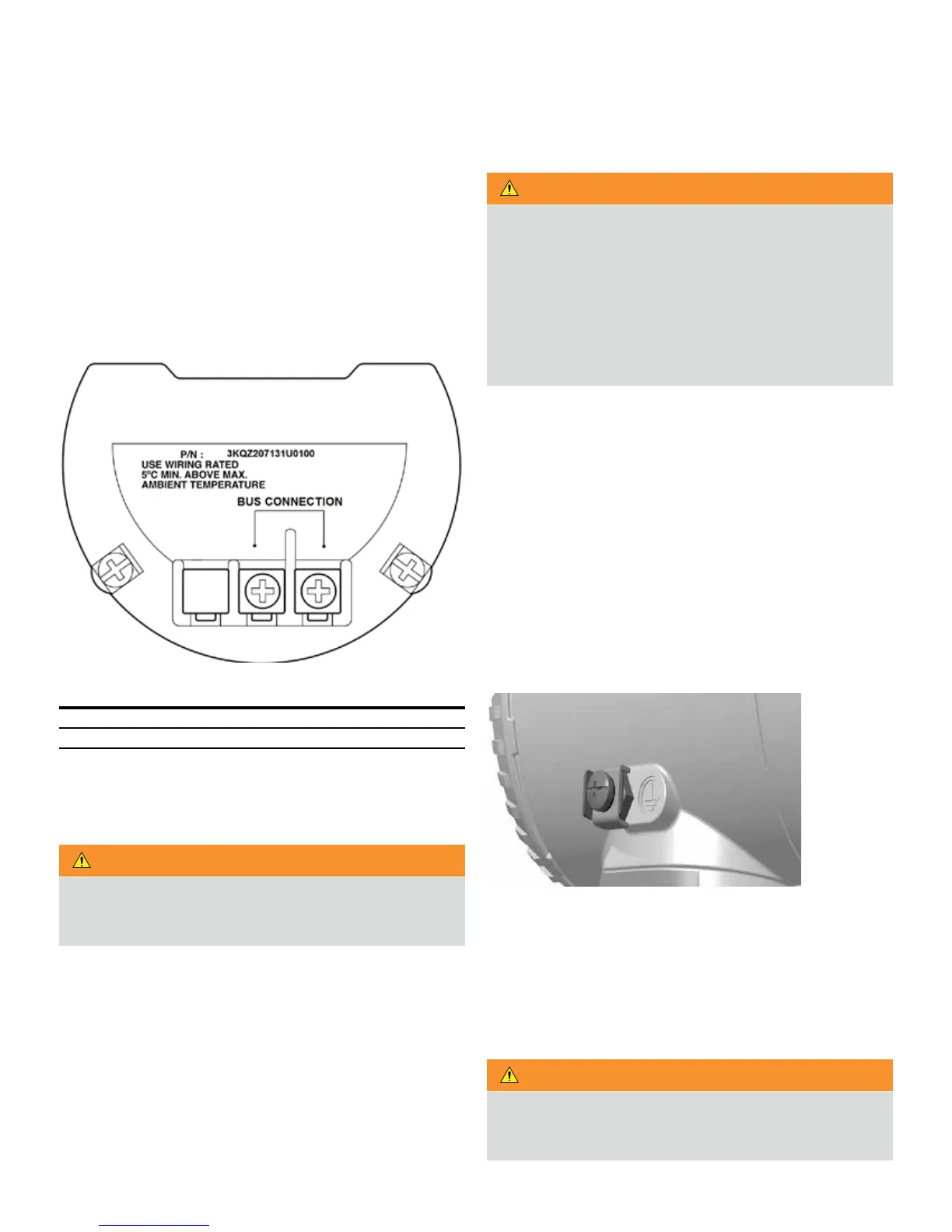
• For Foundation Fieldbus version, the terminal without surge
protection is as below:
Figure 18 FF Terminal board without surge option
Terminal Function / Comment
Bus Connection Power supply, polarity insensitive
• Remove the housing cover on the field terminals side. The
user needs to then view the indication on the label at the neck
of the housing.
WARNING
In an explosion-proof / flame-proof installation, do not
remove the transmitter covers when power is supplied to
the unit.
• Run the cable through cable gland and the open port.
• Connect the positive lead to the + terminal and the negative
lead to the – terminal.
• Plug and seal the electrical ports. Ensure that upon
completion of the installation, the electrical ports are
properly sealed against entry from rain and / or corrosive
vapors and gases.
WARNING
General risks. Cable, cable gland and unused port plug must
be in accordance with the intended type of protection (for
example, intrinsically safe and explosion-proof) and the
degree of protection (for example, IP6x according to IEC EN
60529 or NEMA 4x). See also the addendum for Ex Safety
Aspects and IP Protection. In particular, for explosion-proof
installation, remove the red, temporary plastic cap and plug
the unused opening with a plug certified for explosion
containment.
• If applicable, install the wiring with a drip loop. Arrange the
drip loop so the bottom is lower than the conduit connections
and the transmitter housing.
• Place the housing cover back, turn it to seat the O-ring into
the housing and then continue to hand-tighten until the cover
contacts the housing, metal-to-metal. In Ex-d (explosion-
proof) installation, lock the cover rotation by turning the set
nut.
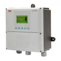
Grounding
A terminal is available on both the outside of the housing and in
the plug for grounding (PE) the transmitter. Both terminals are
electrically connected to one another (see Figure 19).
Figure 19 Ground connection on transmitter housing
All transmitters are supplied with an external ground
connection for protective grounding. Wire this ground
connection to a suitable earth ground. For a transmitter
measuring loop, an earth ground should maintain a resistance
of 5 ohms or less. Use a heavy-duty conductor, at least 15 AWG /
1.6mm
2
Ø.
WARNING
The LMT provides internal and external grounding terminals
for use in installations in accordance to the applicable
regional regulations governing electrical installations.