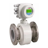
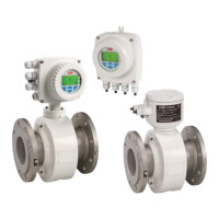
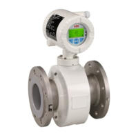
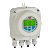
Ex relevant specifications for operation in Div. 2
30 - EN FEX300, FEX500 SM/FEX300/FEX500/FM/CSA-EN
6.2 Electrical data for operation in zones 2, 21, 22 / Div. 2
6.2.1 Devices with HART protocol
When operating in potentially explosive areas, observe the following electrical data for the signal inputs and outputs of the transmitter. For the
correct current output design (active/passive), see the marking contained in the device's terminal box.
Model: FEP315, FEH315 / FEP515, FEH515 or FET325 / FET525
Operating values Type of protection Ex n/NI
Signal inputs and outputs
U
i
[V] I
i
[mA] U
i
[V] I
i
[mA]
Current / HARToutput, active/passive (terminals 31/32)
Load: 250 Ω ≤ R ≤ 650 Ω
30 30 30 30
Digital output DO1, active/passive (terminals 51/52) 30 220 30 220
Digital output DO2, passive (terminals 41/42) 30 220 30 220
Digital input DI (terminals 81/82) 30 10 30 10
All inputs and outputs are electrically isolated from each other and from the supply power.
6.2.2 Devices with PROFIBUS PA or FOUNDATION fieldbus
When operating in potentially explosive areas, observe the following electrical data for the signal inputs and outputs of the transmitter. For the
correct design (PROFIBUS PA or FOUNDATION fieldbus), see the marking contained in the device's terminal box.
For devices in Zone 2 / Div. 2 the bus termination must conform to the FNICO model or the explosion protection regulations, respectively.
Model: FEP315, FEH315 / FEP515, FEH515 or FET325 / FET525
Operating values Type of protection Ex n, NI and FNICO
Inputs and outputs
U
N
[V]
I
N
[mA]
U
i
[V]
I
i
[mA]
P
i
[mW]
C
i
[nF]
C
iPA
[nF]
L
i
[µH]
Digital output DO2, passive (terminals 41/42) 30 220 - - - - - -
Fieldbus (terminals 97/98)
32 30 32
500
1)
7000
1)
1 1 5
1) Single-channel or multi-channel barriers (supply isolators) with resistance characteristic must be used.
6.3 Temperature data for operation in Zone 2 / Div. 2
Model name Surface temperature
FEP315 / FEH315
FEP515 / FEH515
70 °C (158 °F)
FEP325 / FEH325
FEP525 / FEH525
85 °C (185 °F)
FET325 / FET525 70 °C (158 °F)
The surface temperature depends on the fluid temperature.
With increasing fluid temperature > 70 °C (> 158 °F) or > 85 °C (> 185 °F) the surface temperature also increases to the level of the fluid
temperature.
Note
The maximum permissible fluid temperature depends on the lining and flange material, and is limited by the operating values in Table 1 and the
explosion protection specifications in Tables 2 ... n.

 Loading...
