Ex relevant specifications for operation in Div. 2
SM/FEX300/FEX500/FM/CSA-EN FEX300, FEX500 EN - 29
6 Ex relevant specifications for operation in Div. 2
6.1 Electrical connection
6.1.1 Flowmeter sensor and transmitter in Div. 2, or transmitter outside the hazardous area
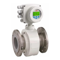
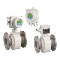
FEP315 / FEP515, FEH315 / FEH515, FEP325 / FEP525, FEH325 / FEH525 flowmeter
sensors and FET325 / FET525 transmitters (Div. 2)
FET321 / FET521 transmitter outside the
hazardous area
A = Transmitter, B= Sensor
Fig. 15: HART, PROFIBUS PA and FOUNDATION fieldbus protocol
Change from one to two colu mns
Power supply connections
AC power supply
Terminal Function / Notes
L
Live / Phase
N
Neutral
PE /
Protective earth (PE)
DC power supply
Terminal Function / Notes
1+
+
2-
-
PE /
Protective earth (PE)
Sensor cable terminal connections
Only on remote mount design.
Terminal Function / Notes Wire color
M1
Magnet coil Brown
M2
Magnet coil Red
D1
Data line Orange
D2
Data line Yellow
/ SE
Shield -
E1
Signal line Violet
1S
Schield for E1 -
E2
Signal line Blue
2S
Schield for E2 -
3
Measurement potential Green
Output connections
Terminal Function / Notes
31 / 32
Current / HART output
The current output is available in "active" or "passive"
mode.
97 / 98
Digital communication
PROFIBUS PA (PA+ / PA-) or FOUNDATION
fieldbus (FF+ / FF-) in acc. with IEC 61158-2.
51 / 52
Digital output DO1 active / passive
Function can be configured locally as „Pulse Output"
or „Digital Output". Factory setting is „Pulse Output".
81 / 82
Digital input / contact input
Function can be configured locally as „External
output switch-off“, „external totalizer reset“, „external
totalizer stop“ or „other“.
41 / 42
Digital output DO2 passive
Function can be configured locally as „Pulse Output"
or „Digital Output". Factory setting is „Digital Output",
flow direction signaling.
PA
Potential Equalization (PA)
Functional ground
(only for transmitter outside the hazardous area)
Change from one to two colu mns
Change from one to two colu mns
Note
The housing for the transmitter and flowmeter sensor must be
connected to the potential equalization PA. The operator must ensure
that when connecting the protective conductor (PE) no potential
differences can occur between protective conductor and potential
equalization (PA).
FM-compliant installations must be performed in accordance with
"Installation of Intrinsically Safe Systems for Hazardous (Classified)
Locations" (ANSI/ISA RP 12.6) and "National Electric Code®"
(ANSI/NFPA 70 Sections 504 and 505).
For devices with remote mount design for use in FM / cFM Div. 1 or
FM / cFM Div. 2 the signal cable between the flowmeter sensor and
the transmitter must have a minimum length of 5 m (16.4 ft).
A temperature of 70 °C (158 °F) at the cable entry is assumed for the
Ex calculations. Therefore, the cables used for the supply power and
the signal inputs and outputs must have a minimum specification of
70 °C (158 °F).
Change from one to two colu mns
G00873-02
PA
31 32
A
24 V
51 52 81 82
41 42
LN
1+ 2-
M1 M2 D1 D2
3
2S
E2 E1
1S
M1 M2 D1 D2
3
E2 E1
B
PE
PA
97 98
41 42
PA+ PA-
FF+ FF-
+
-
+
-
+
-
+
-
+
-
HART
PROFIBUS PA, FOUNDATION fieldbus
PA /
2S 1S
PA
PA
PA
FEP315 /
FEP515
FEP325 / FEP525
FEH325 / FEH525 FET325 / FET525 FET321 / FET521
PA
FEH315 /
FEH515

 Loading...
