Main Slot ID Content options
Case X130 AI/BI module Only with configuration D:
3 phase voltage inputs (60...210 V)
1 residual voltage input (60...210 V)
4 binary inputs
AI/RTD/mA module
Only with configuration D:
3 phase voltage inputs (60...210 V)
1 residual voltage input (60...210 V)
1 generic mA input
2 RTD sensor inputs
Optional BIO module
Optional for configuration C:
6 binary inputs
3 SO contacts
X000
Communication module See the technical manual for details about different
types of communication modules.
Rated values of the current and voltage inputs are basic setting parameters of the
protection relay. The binary input thresholds are selectable within the range 16…176
V DC by adjusting the binary input setting parameters.
See the installation manual for more information about the case and
the plug-in unit.
The connection diagrams of different hardware modules are presented in this manual.
Table 3: Input/output overview
Std.
conf.
Order code digit Analog channels Binary channels
5-6 7-8 CT VT Combi
sensor
BI BO RTD mA
C AC
AD
4 - - 12 4 PO
+ 6 SO
- -
AF
4 - - 18 4 PO
+ 9 SO
- -
D
FE / FF AD
4 5 - 12 4 PO
+ 6 SO
2 1
AE / AF AG
4 5 - 16 4 PO
+ 6 SO
- -
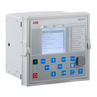
2.4 Local HMI
The LHMI is used for setting, monitoring and controlling the protection relay. The
LHMI comprises the display, buttons, LED indicators and communication port.
Section 2 1MRS758127 C
RED615 overview
16 RED615
Application Manual

 Loading...