3.3.2 Functions
RED615
AT REMOTE
END
ALSO AVAILABLE
- Binary Signal Transfer function (BST)
- Disturbance and fault recorder
- Event log and recorded data
- Local/Remote push button on LHMI
- Self-supervision
- Time synchronization: IEEE 1588 v2,
SNTP, IRIG-B
- User management
- Web HMI
LINE DIFFERENTIAL PROTECTION AND CONTROL RELAY
PROTECTION
LOCAL HMI
STANDARD
CONFIGURATION
REMARKS
Optional
function
No. of
instances
Alternative
function to be
defined when
ordering
R
L
ClearESC
I
O
Configuration A
System
HMI
Time
Authorization
R
L
ClearESC
I
O
U12 0. 0 kV
P 0.00 kW
Q 0.00 kVAr
IL2 0 A
A
With in-zone power transformer support
RED615
C
CONTROL AND INDICATION
1)
MEASUREMENT
Analog interface types
1)
Current transformer
Voltage transformer
1)
Conventional transformer inputs
Object Ctrl
2)
Ind
3)
CB
DC
ES
1)
Check availability of binary inputs/outputs
from technical documentation
2)
Control and indication function for
primary object
3)
Status indication function for
primary object
1 -
2 3
1 2
- I, Io
- Limit value supervision
- Load profile record
- Symmetrical components
4
-
Master Trip
Lockout relay
94/86
COMMUNICATION
Protocols:
IEC 61850-8-1
Modbus
®
IEC 60870-5-103
Interfaces:
Ethernet: TX (RJ45), FX (LC)
Serial: Serial glass fiber (ST),
RS-485, RS-232
Redundant protocols:
HSR
PRP
RSTP
CONDITION MONITORING
AND SUPERVISION
3Ith>T/G/C
49T/G/C
CCM_L 3I, I2
CCM_L 3I, I2
3I
Io
Io
Io
3I
3IB
3IB
GUID-E15D5C7F-A809-48B6-8C7E-54BA598228EA V1 EN
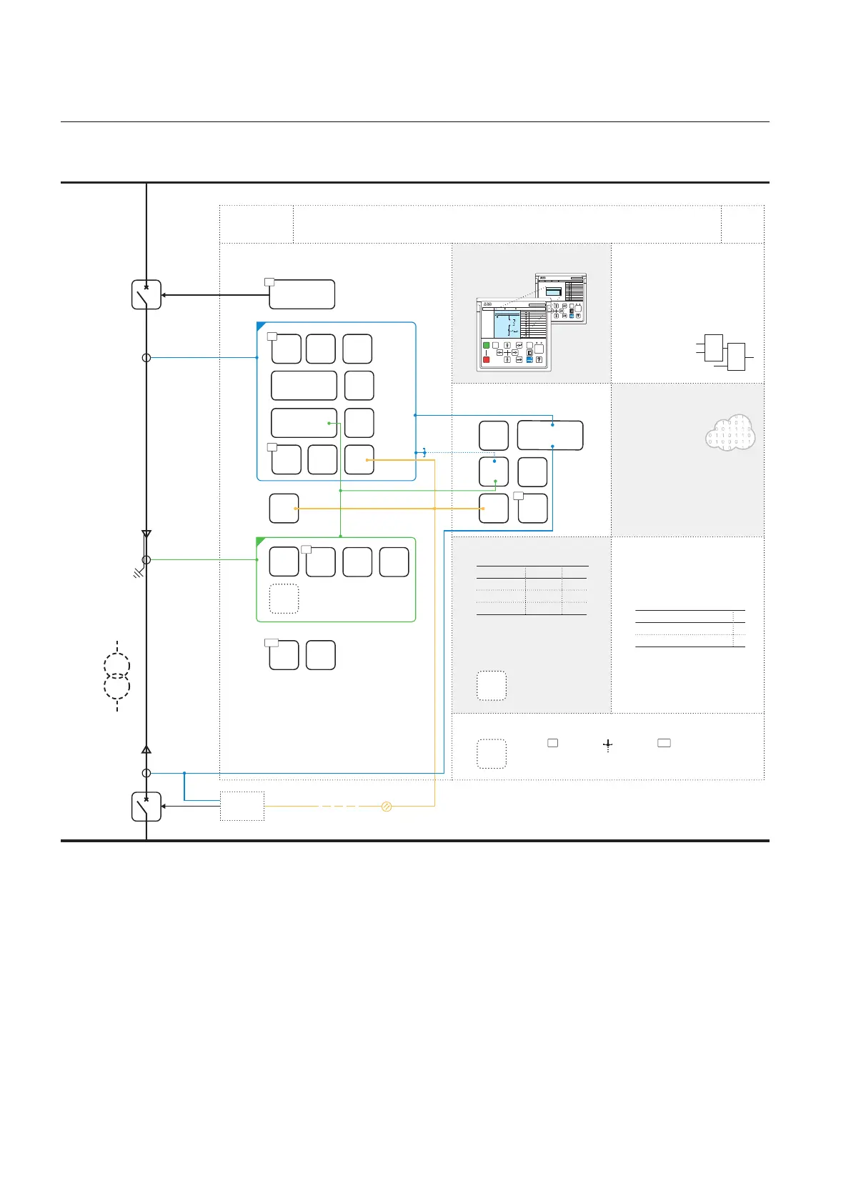
Figure 14: Functionality overview for standard configuration C
3.3.2.1 Default I/O connections
Connector pins for each input and output are presented in the Protection relay's
physical connections section.
Section 3 1MRS758127 C
RED615 standard configurations
38 RED615
Application Manual
 Loading...


