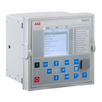
3.2 Connection diagrams
RED615
L1
L2
L3
X130
1
2
3
4
5
6
BI 4
BI 3
BI 2
BI 1
BI 6
BI 5
8
9
7
X130
12
10
11
15
13
14
18
16
17
SO3
SO2
SO1
X1
LAN
X5
1
2
3
4
5
6
7
8
9
B/-
A/+
B/-
A/+
/ TX
/ RX
GND
GNDC
X16
Line Differential Protection Communication
X2
LAN
IRIG-B -
IRIG-B +
AGND
1) 4)
1) 3)
1) 3)
X12
RX
TX
S1
S2
P1
P2
S1
S2
P1
P2
1) 5)
16
17
19
18
X100
6
7
8
9
10
11
12
13
15
14
2
1
3
4
5
22
21
23
24
SO2
TCS2
PO4
SO1
TCS1
PO3
PO2
PO1
IRF
Uaux
20
Protection
Core
Earth Fault and
CT Supervision
Reference Current
6)
Positive
Current
Direction
X120
1
2
3
4
5
6
7
8
9
10
11
12
13
14
Io
IL1
IL2
BI 4
BI 3
BI 2
BI 1
IL3
1/5A
N
1/5A
N
1/5A
N
1/5A
N
X110
3
4
5
6
7
8
9
10
BI 6
BI 5
BI 4
BI 3
BI 2
BI 8
BI 7
12
13
11
BI 1
1
2
X110
16
14
15
19
17
18
22
20
21
SO3
SO2
SO1
23
SO4
24
2)
1) Optional
2) The IED features an automatic short-circuit
mechanism in the CT connector when plug-in
unit is detached
3) 100BaseFx / LC or 100BaseTx / RJ-45
4) RS-485 serial bus
5) Fibre Optic (ST) Serial Bus
6) In configuration A used only for CT supervision
1)
GUID-439DDAA0-2B19-487B-997E-AEA8E2EF7A51 V1 EN
Figure 12: Connection diagram for the C configuration
1MRS758127 C Section 3
RED615 standard configurations
RED615 35
Application Manual

 Loading...