1MDU07205-YN rev. F
REF601 CEI
User’s manual
15
2.4.2 Recorded data & Trip counter
The relay stores records of analog values for two trip events in non-volatile memory.
The fault recording is triggered by the trip signal of protection function. A sample of
analog value is recorded for every power frequency cycle. Fifteen such samples are
recorded, fi ve before the trip and ten after the trip event. These records enable the
user to analyze the two most recent power system events. Each record includes the
current values for three phases and earth current. The oldest recording is lost when
a new fault recording is made.
The relay records the number of phase and earth fault trip events into dedicated trip
counters. These trip counters can not be reset by the user and are stored in non-
volatile memory. The recorded information is store in non-volatile memory and can be
accessed locally via the user interface on the relay front panel and can be uploaded
for subsequent fault analysis.
2.4.3 Event Log
To collect sequence-of-events (SoE) information, the relay incorporates a non-volatile
memory to store fi ve event logs. Each event log includes a snapshot of Analog values,
Protection operation status, Binary I/O status and Relay fault code. The event logs are
stored sequentially, the most recent being fi rst and so on. The non-volatile memory
retains its data also in case the relay temporarily loses its auxiliary supply.
The event log facilitates detailed pre- and post-fault analysis of feeder faults and dis-
turbances. The SoE information can be accessed locally via the user interface on the
relay front panel or remotely via the communication interface of the relay.
2.4.4 Access Control
To protect the relay from unauthorized access and to maintain the integrity of informa-
tion, the relay is armed with a three level, role-based user authentication system with
individual password for the operator, engineer and administrator level. The password
is a combination of different navigation keys.
2.5 Power Supply
To be able to operate the relay needs a secured auxiliary voltage supply. The power
supply module forms the voltages required by the protection relay module and the
auxiliary relays.
The power supply board is having universal 24-240V AC / DC input voltage range. It
is galvanically isolated switch mode power supply. It is implemented using fl y-back
topology where output voltages (+12V and -15V) are obtained using an isolation
transformer. The output voltages are sensed through optical isolation
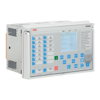
REF601 overview