1MDU07205-YN rev. F
REF601 CEI
User’s manual
30
Protection Functions
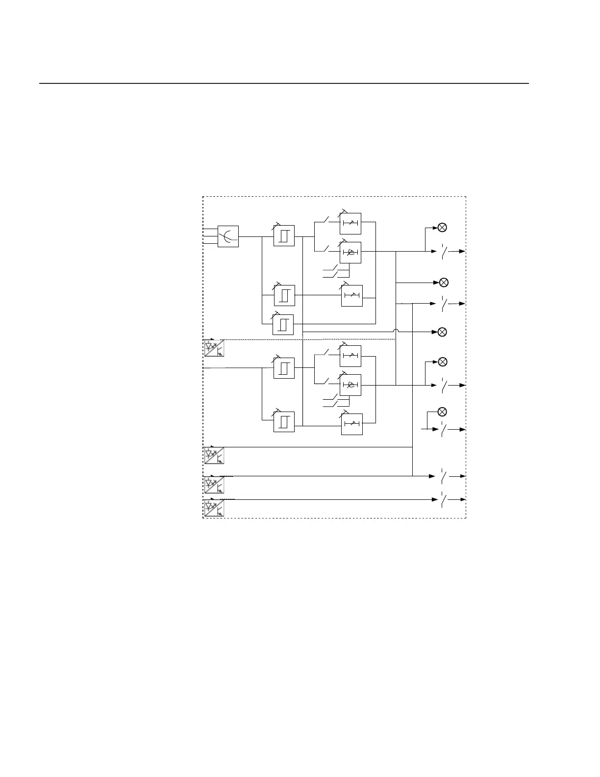
4.6 Signal Diagram
The fi gure below schematically illustrates the analogue input, binary input / output
and LED indications.
Fig. 6 – Signal diagram of relay REF601
Analogue input:
o L1, L2, L3 Energizing sensor input for phase L1, L2, L3
o Io Earth current input 1A through CBCT for external
earth measurement
Trip 2 / Breaker
Open command
Breaker Close
command
Breaker
Open
Breaker
Close
L1
L2
L3
I>,,I>>,I>>>
Signalling
I>>
I>>>
Io
t>
K
t>>
Trip Ip
Io>>
to>
K
to>>
Io>
Trip Io
Trip 1