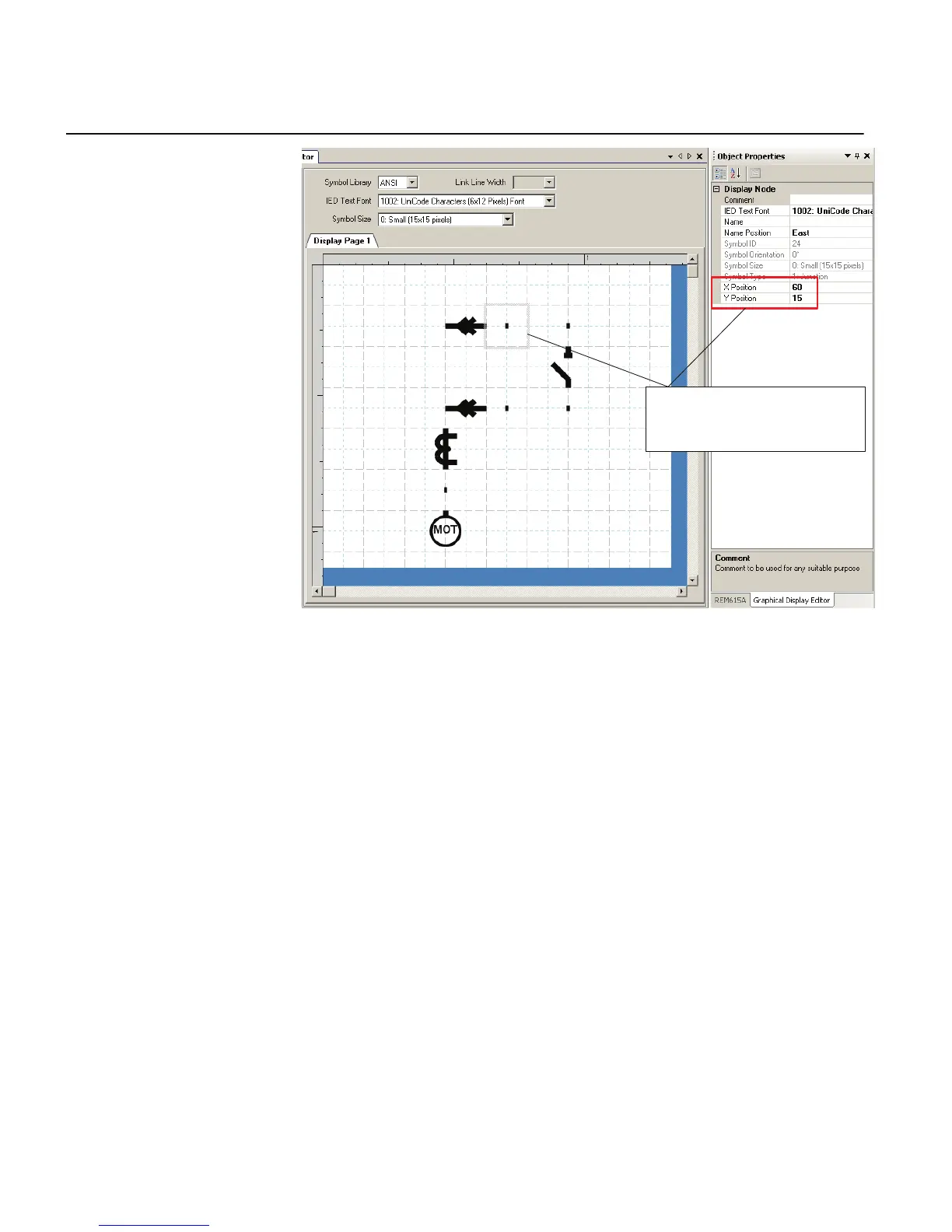
Use X and Y cordinates from the Object
Properties window for every symbol to
adjust the singleline diagram.
GUID-BB90E914-7B02-4D1E-A385-FB6D6305869C-ANSI V1 EN
Figure 55: Graphical Display Editor: adding single-line diagram symbols into
a display page
6.1.1.11 Drawing lines to create links
After the apparatus symbols are placed, lines can be drawn to create links.
1. To draw a line, move the mouse pointer to the center of the connection point
(visible in two circles at the end points of a line).
2. Click to start and move the mouse pointer to the destination connection point.
3. Center the mouse pointer again and click to drop the line.
Section 6 1MRS240044-IB A
LHMI engineering
92 REF615R
Engineering Manual