L1
(A)
L2
(B)
L3
(C)
Protected Object
CT 1500/5
Star/Wye
Connected
7
8
9
10
11
12
1
2
3
4
5
6
AI01 (I)
AI02 (I)
AI03 (I)
AI04 (I)
AI05 (I)
AI06 (I)
IED
X1
R1
1
2
4 5
U
R2
1
3
4
2
1 2 3
N
1-Ph Plate with Metrosil and Resistor
N
L1
(A)
L2
(B)
L3
(C)
CT 1500/5
=IEC07000194=5=en=Original.vsdx
SMAI2
BLOCK
REVROT
^GRP2L1
^GRP2L2
^GRP2L3
^GRP2N
G2AI3P
G2AI1
G2AI2
G2AI3
G2AI4
G2N
1
2
3
4
5
6
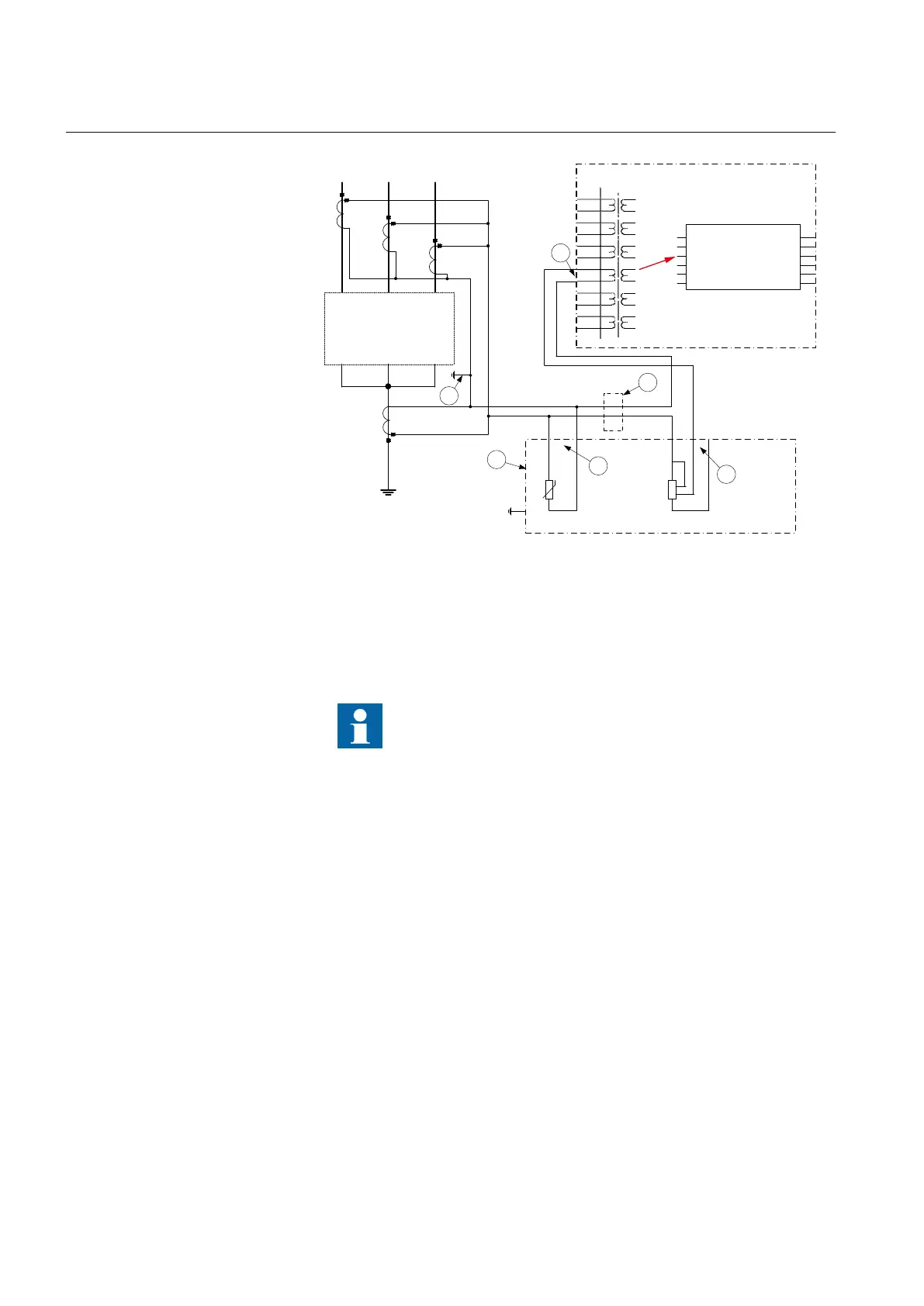
IEC07000194 V5 EN
Figure 62: CT connections for restricted earth fault protection
Pos
Description
1 Scheme earthing point
Ensure that only one earthing point exists in this scheme.
2 One-phase plate with stabilizing resistor and metrosil. Protective earth is a separate 4 mm screw
terminal on the plate.
3 Necessary connection for the metrosil.
4 Position of optional test switch for secondary injection into the high impedance differential IED.
5 Necessary connection for stabilizing resistor.
6 How to connect the high impedance restricted earth fault protection scheme to one CT input in
IED.
7.2.4 Setting guidelines
The setting calculations are individual for each application. Refer to the different
application descriptions below.
7.2.4.1 Configuration
The configuration is done in the Application Configuration tool.
Section 7 1MRK 502 071-UEN -
Differential protection
158 Generator protection REG670 2.2 IEC and Injection equipment REX060, REX061, REX062
Application manual

 Loading...


