Operating Instructions SYN 5201/SYN 5202
Document No Art Part Language Revision page
abb
ABB Switzerland Ltd
3BHS109762 E01
en D 10
Template: CHIND Techn doc stand, A4 P de, R1.DOT; Filename: 3BHS109762E01 D.doc; Print: 12/6/2011 5:48:00 PM; Save: 12/1/2011 2:37:00 PM; CHIND No. 3BHS109763 ZAB D14 Rev. -; I-Q
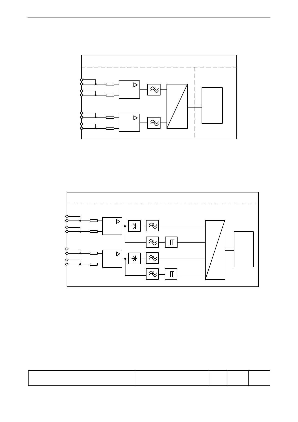
Voltage measurement (SYN 5202: channel 1)
The two input voltages U1 and U2 are passed to the processor via high-impedance input
resistors, differential amplifiers, low-pass filters and A/D converters.
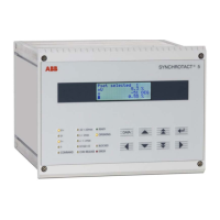
Voltage measurement channel 2 (SYN 5202 only)
The two input voltages U1 and U2 are passed through high-impedance input resistors
and differential amplifiers. The signal for the amplitude value is formed from this by
conversion and filtering . For zero-passage detection, the signal is filtered and passed
through a comparator. The signals prepared in this way are passed to the processor via
the A/D converter.
S00002
U2
U1
A
D
SYNCHROTACT 5
PCB: SYN 5012 PCB: SYN 5011
CPU
S00003
U2
U1
SYNCHROTACT 5
A
D
CPU
Amplitude
Amplitude
crossing
Zero-
crossing
Zero-
PCB: SYN 5013