Operating Instructions SYN 5201/SYN 5202
Document No Art Part Language Revision page
abb
ABB Switzerland Ltd
3BHS109762 E01
en D 81
Template: CHIND Techn doc stand, A4 P de, R1.DOT; Filename: 3BHS109762E01 D.doc; Print: 12/6/2011 5:48:00 PM; Save: 12/1/2011 2:37:00 PM; CHIND No. 3BHS109763 ZAB D14 Rev. -; I-Q
7.1.2 Display
The display is permanently active in BLOCKED & ERROR and OPERATING statuses.
Otherwise the display is dark. As soon as any key is pressed, the display is activated
and remains active for 30 s after the last key operation in READY status, and for 5
minutes in BLOCKED status.
Display
type
Example Comments
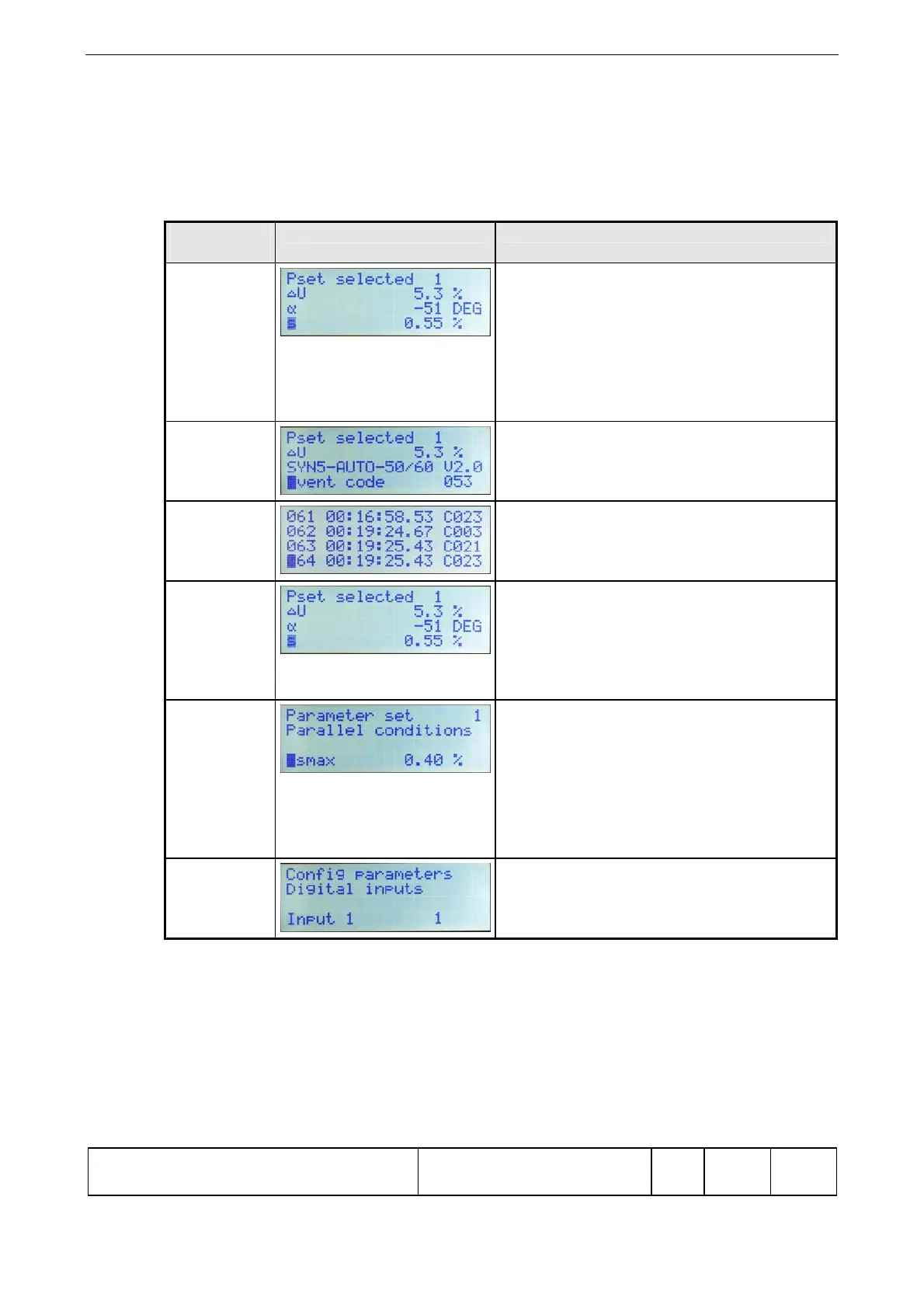
Standard
display
(following
initialisation)
fter the auxiliary voltage is switched on or
after a reset command, the processor is re-
initialised.
The standard display of actual values
shown on the left then appears. The
selected parameter set is displayed on the
line “Pset selected” or, if none is selected,
a question mark.
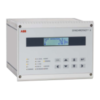
Fault
present
The last value of the fault logger is
displayed on the bottom line. The installed
software version is displayed on the
second line from the bottom.
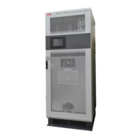
Event logger The line number appears on the left for
ease of orientation. This is followed by the
timestamp in hours, minutes and seconds.
On the right is the code Cyyy.
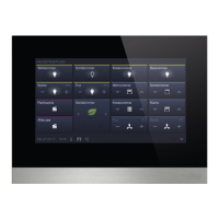
Actual value
block
In the actual value block, the values which
are to be displayed can be selected on
lines 2, 3 and 4. This user-defined display
is retained after use, but switches back to
standard following interruption of the
auxiliary voltage.
Parameter
sets
The current parameter set is displayed in
the first line.
The second line shows the current parame-
ter group.
The third line is normally empty.
The fourth line is the working line and
displays the parameters and their setting
values.
Configurable
inputs /
outputs
The inputs I1 to I7 and outputs O1 to O7
can be configured here by changing their
values (according to the table).