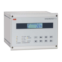
Operating Instructions SYN 5201/SYN 5202
Document No Art Part Language Revision page
abb
ABB Switzerland Ltd
3BHS109762 E01
en D 14
Template: CHIND Techn doc stand, A4 P de, R1.DOT; Filename: 3BHS109762E01 D.doc; Print: 12/6/2011 5:48:00 PM; Save: 12/1/2011 2:37:00 PM; CHIND No. 3BHS109763 ZAB D14 Rev. -; I-Q
Frequency matcher with variable intervals
The function INVERSE f changes the way the frequency matcher functions. The pulses
are now always the same length, but the intervals are inversely proportional to the slip.
Pulse length: adjustable by means of the parameter tp fmin: tp = tp fmin
Pause interval: is calculated according to the following formula (can not be set as a
parameter):
s
sfff
ts 30
*1
1
21
1
2.2.3 Monitoring of paralleling conditions
The monitoring of the paralleling conditions can be divided into these parallel-functioning
blocks:
voltage-carrying lines
no-voltage lines
Paralleling of two voltage-carrying lines
The monitoring of the paralleling conditions enables a paralleling command (CHK
RELEASE) if the following conditions are fulfilled simultaneously:
the phase-angle difference is within the tolerance band
the slip is within the tolerance band
the voltage difference is within the tolerance band
the voltage does not fall below minimum voltage
the maximum voltage is not exceeded
the device is in operating status (OPERATING)
nominal frequency deviation 5 Hz
Paralleling of no-voltage lines (dead bus)
A special case for the monitoring is the paralleling of no-voltage lines. A paralleling
command release is only issued if the external release signal is active and the
measuring logic enables the release at the same time. The release by the measuring
logic can be enabled if both voltages are within one of the permitted ranges. The dead
bus range can be defined as permissible for one, the other or both measuring voltages
by means of the parameters U1not, U2not and 1*2not.
Releasing signal
S00007
U1
U2
+
U0max
&
&
&
U1not
U2not
OR
&
1*2not
Releasing signal
Dead bus blocking logic and parameters