Operating Instructions SYN 5201/SYN 5202
Document No Art Part Language Revision page
abb
ABB Switzerland Ltd
3BHS109762 E01
en D 52
Template: CHIND Techn doc stand, A4 P de, R1.DOT; Filename: 3BHS109762E01 D.doc; Print: 12/6/2011 5:48:00 PM; Save: 12/1/2011 2:37:00 PM; CHIND No. 3BHS109763 ZAB D14 Rev. -; I-Q
4.3.2 Configuring Modbus RTU
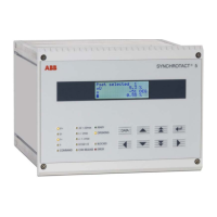
The configuration of the Modbus RTU is carried out using 14 DIP switches. The three
LEDs on the left next to the DIP switches are used for the status display.
The device has to be restarted each time the configuration is changed (switch auxiliary
voltage off and on again).
If the SYNCHROTACT 5 device is configured in RS485 mode and is the last component
on the bus, the blue switch (SWITCH) to the left of the LED‘s has to be set to ON in
order to prevent reflections on the bus line.
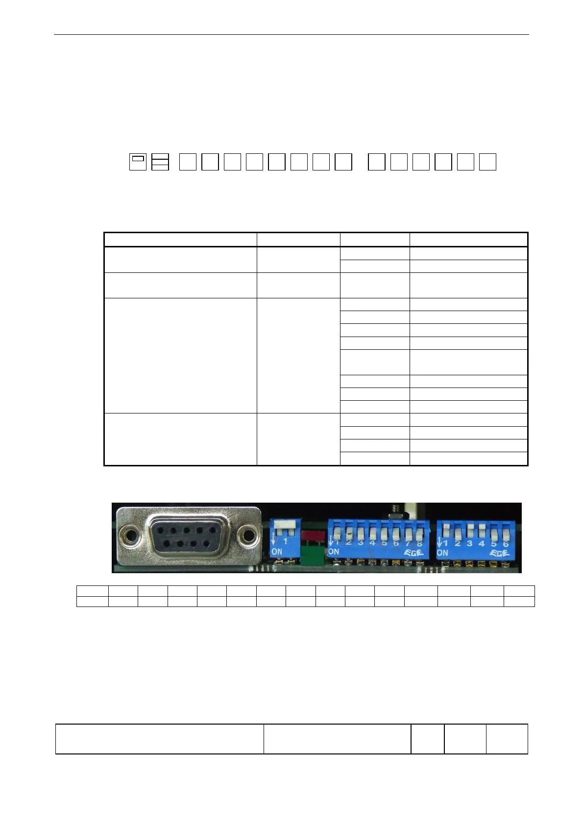
Function DIP no. DIP value Configuration
Electrical mode DIP 0 0 RS485
1 RS232
Selection of slave address DIP 1 – DIP 8 MSB - LSB Valid range
1-247
Selection of Baudrate DIP 9 / 10 / 11 000 1200
001 2400
010 4800
011 9600
100 19200
(factory setting)
101 38400
110 50000
111 Not supported
Selection of parity mode DIP 12 / 13 00 None
01 Odd
10 Even
11 Not used
Example:
Switch DIP0 DIP1 DIP2 DIP3 DIP4
DIP5
DIP6
DIP7
DIP8
DIP9
DIP10 DIP11 DIP12
DIP13
OFF
0 0 0 0 0 0 0 0 1 0 1 1 0 0
SWITCH OFF
Electrical mode RS485
Slave address: 1
Baud rate: 9600
Parity: None
DIP0 DIP1 DIP13DIP12
1
0
1
0
LEDS DIP10 DIP11DIP9DIP8DIP7DIP6DIP5DIP4DIP3DIP2SWITCH
ON
OFF
Note
Note