Operation Manual / TPL69-A10 / -A30 ... TPL77-A10 / -A30
Dismantling and fitting nozzle ring at
turbine end
Page 118
All rights reserved.
December 2016 HZTL2481_EN Revision B
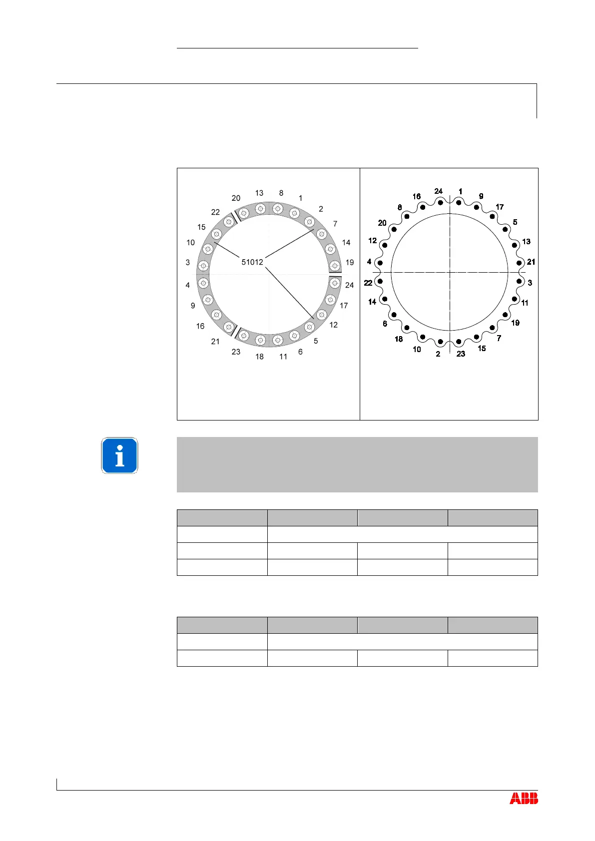
Tightening procedure and order:
Segment connection
Begin with two middle screws of
individual segments and then
continue outwards alternately.
Flange connection
Tighten screws crosswise
Screw tightening sequence
The screw positioning numbers must be marked on the component.
This enables simple and efficient tightening.
Screw in all screws hand-tight
Step 2 130 190 240
Step 1 Screw in all screws hand-tight
Beginning with screw 1, tighten all screws in a clockwise direction with
tightening torque from step 3.
Remove lifting gear from gas inlet casing (51001).
Connect cleaning pipe (if present) and attach insulation to gas inlet
casing (51001).
Tightening torques for
screws (61044) [Nm]
with spiral-wound gasket
Tightening torques for
screws (61044) [Nm]
without spiral-wound gas-
ket
Checking the tightening
torque
 Loading...