- 45 -
000325BG
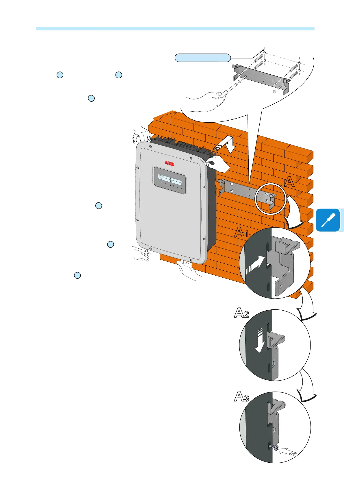
5 - Installation
During installation do not place the
inverter
10
with the front cover
04
facing towards the ground.
•
Position the bracket
13
so that it is
perfectly level on the wall and use it
as a boring template.
• Make the 4 holes necessary, using
a drill with a 10 mm. diameter bit. The
depth of the holes must be around 70
mm.
• Secure the bracket to the wall with
the no. 4 10 mm wall plugs supplied
with it.
•
Attach the inverter by inserting the
two tabs on the bracket
13
into the
2 holes on the inverter (gure A
1 and
A2).
•
Secure the inverter to the bracket
by screwing the lock screws
14
on
both sides of the inverter (gure A3).
• Unscrew the 8 screws and open
the front cover
04
,
as described in
the following paragraph, to make all
necessary connections. The cover
is equipped with xed hinges and
must not be removed. To open the
cover, follow the instructions in
the next paragraph
• Once the connections have been
made proceed to closing the cover by
tightening the 8 screws on the front,
adhering to the sequence and tighte-
ning torque (see specic paragraph
on "Closing the front cover").
Wall mounting
4 x Ø 10 mm
A
A1
A2
A3
TRIO
POWER ALARM GFI ESC UP DOWN ENTER

 Loading...


