- 61 -
000328BG
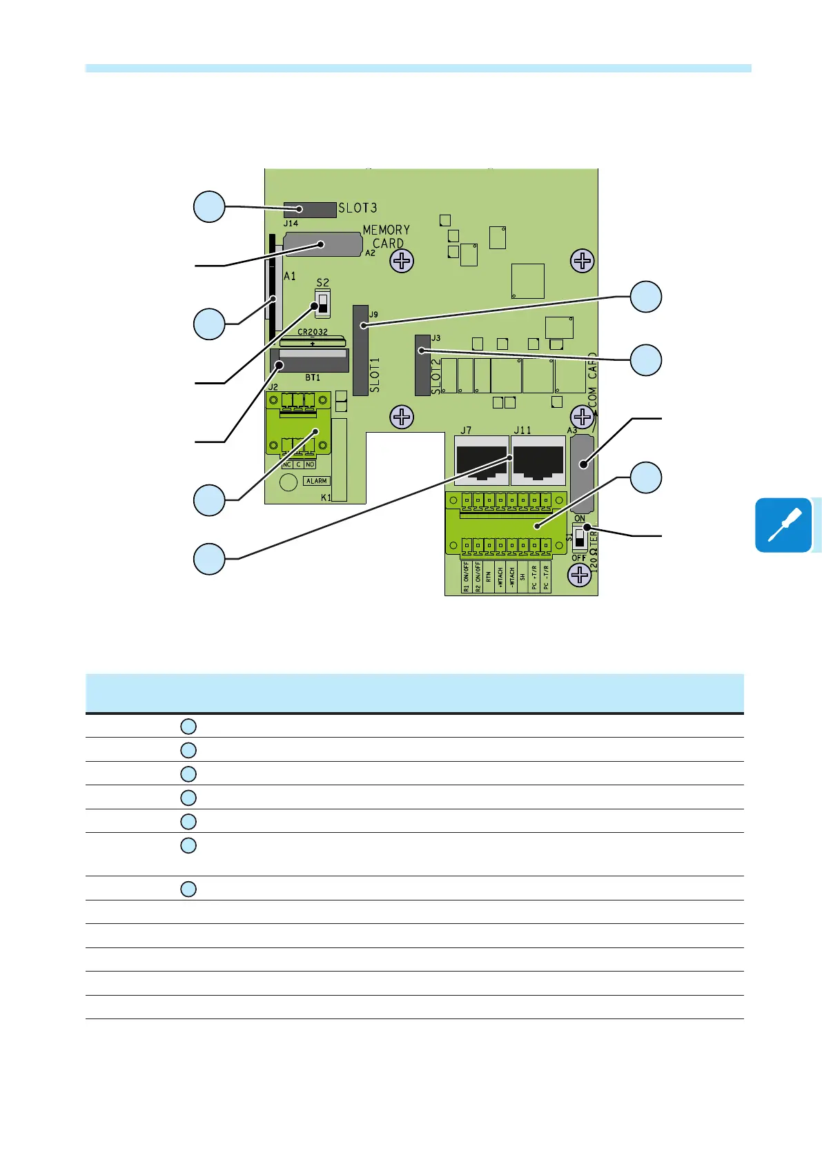
5 - Installation
Communication and control board
1
a04
a05
a01
a02
a03
24
25
29
28
27
26
30
communication and control board
Ref.
inverter
Ref.
manual
Description
J14
24
SLOT 3 - Connector for WIFI modules installation (NOT ACTIVE)
A1
25
SD CARD housing
J2
26
Connection to the multi-function relay
J9
27
SLOT 1 - Connector for radio module or Ethernet card installation
J3
28
SLOT 2 - Connector for PMU card installation
J4
29
Connection of the RS485 (PC) line and of the remote ON/OFF and of the Tachometer
signal (WIND version)
J7 and J11
30
Connection of the RS485 (PC) line on RJ45 connector
A2 a01 Inverter data memory card housing
S2 a02 Switch to set the inverter to normal or service mode
BT1 a03 Battery housing
A3 a04 RS485 (PC) communication card housing
S2 a05 RS485 line (PC) termination resistance selector switch

 Loading...


