- 72 -
000331BG
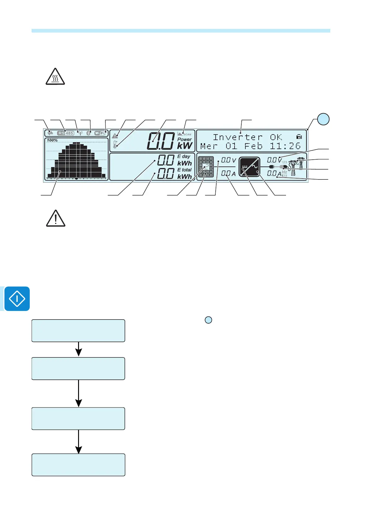
7 - Operation
Commissioning
Do not place objects of any kind on the inverter during operation!
Do not touch the heat sink while the inverter is operating!
Some parts may be very hot and could cause burns.
DC
AC
b02 b03 b04 b05 b06 b08 b09b07b01
b11 b12b13 b24 b14 b15 b16 b17 b18
b19
b21
b20
b22
b10
01
Before proceeding with commissioning, make sure you have carried out all the checks and
verications indicated in the section on preliminary checks.
The procedure for commissioning the inverter consists of the following
steps:
• Close the AC disconnect switch to supply the inverter with the grid
voltage
• Close the DC disconnect switch to supply the inverter with the photo-
voltaic generator voltage.
If the inverter is equipped with a DC disconnect switch (-S models), turn
the DC disconnect switch
14
to the ON position.
• When the inverter is connected to the power supply, the display will
show a guided conguration procedure. Press ENTER to set the fol-
lowing:
- Inverter date and time
- Parallel or independent mode conguration of the input channels
The inverter is shipped from the factory with the input channels set to
INDEPENDENT. Should you decide to use the channels in PARALLEL
mode, you should t the special jumpers supplied and select the correct
input conguration mode
- Selection of grid standard and corresponding display language.
Config. Wizard
ENTER to START
Time hh:mm
Date DD MMM YYYY
Input Mode
PARALLEL/INDEP
GRID=Xxxxxxxx
Lang=Xxxxxxxx
ENTER
ENTER
ENTER

 Loading...


