- 74 -
000331BG
7 - Operation
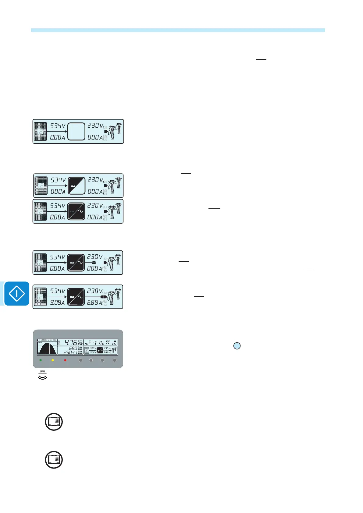
• The inverter checks the grid parameters. Icon b22, which represents the
distribution grid, can have the following statuses:
- Blank, if there is no grid voltage.
- Flashing, if there is grid voltage, but it is outside the range required by
the installation country standard.
- Steady, if the grid voltage it is within the range required by the installa-
tion country standard. In this condition, the inverter starts the grid con-
nection sequence.
This verication can take several minutes (from a minimum of 30 secon-
ds up to several minutes), depending on the grid conditions and settings
relative to the country standard
• At this point icon b17 will ash; this indicates the start-up of the DC-DC
(booster) circuit. This icon will remain on and steady when the DC-DC
circuit is operating normally (this icon usually ashes only for a few se-
conds).
Immediately after this, icon b18, which indicates the DC-AC (inverter)
circuit, will also behave normally.
• Immediately after this the grid connection will start. During this stage
the icons on line b21 will be displayed in sequence until the inverter is
connected. After the inverter is connected, all the icons on line b21 will
remain on and steady.
If the inverter disconnects from the grid, the icons in the left-hand part
(cable and plug) of line b21 will stay on.
• Once the connection sequence has been completed, the inverter starts
to operate and indicates that it is operating correctly by means of a sound
and the green LED on the LED panel
02
coming on steady. This means
there is sufcient solar radiation to feed power into the grid.
• If the grid check does not give a positive result, the unit will repeat the
procedure until all the parameters required for grid connection (grid volta-
ge and frequency, insulation resistance) are within the range. During this
procedure, the green LED ashes.
After the inverter has started for the rst time, it may be congured from the display menu or
by using the dedicated Aurora Manager LITE software.
To address any problems that may occur during the initial stages of operation of the system
and to ensure the inverter remains fully functional, you are advised to check for any rmwa-
re updates in the download area of the website www.abb.com/solarinverters or https://regi-
stration.abbsolarinverters.com (instructions for registering on the website and updating the
rmware are given in this manual)
DC
AC
DC
AC
DC
AC
DC
Inverter not connected to the grid
Inverter connected to the grid
Vgrid OK
BEEP
POWER ALARM GFI ESC UP DOWN ENTER
DC
AC

 Loading...


