Electrical connection
14 TTR200 OI/TTR200-EN
Pos: 14.5 /Überschri ften/1.1/1-spa ltig/A - C/Anschlussbe legung @ 16\mod_1199260233 671_3101.doc @ 146854
5.2 Pin configuration
Pos: 14.6 /Überschri ften/1.1.1/1-spal tig/Versorgungs- / Sensoranschluss @ 16\ mod_1199260387640_3101. doc @ 146877
5.2.1 Supply voltage / sensor connection
Pos: 14.7 /Elektri scher Anschluss/Temper atur/TTR200/Anschl ussplan (BA) @ 18\mod_12 03682458036_3101.doc @ 164662
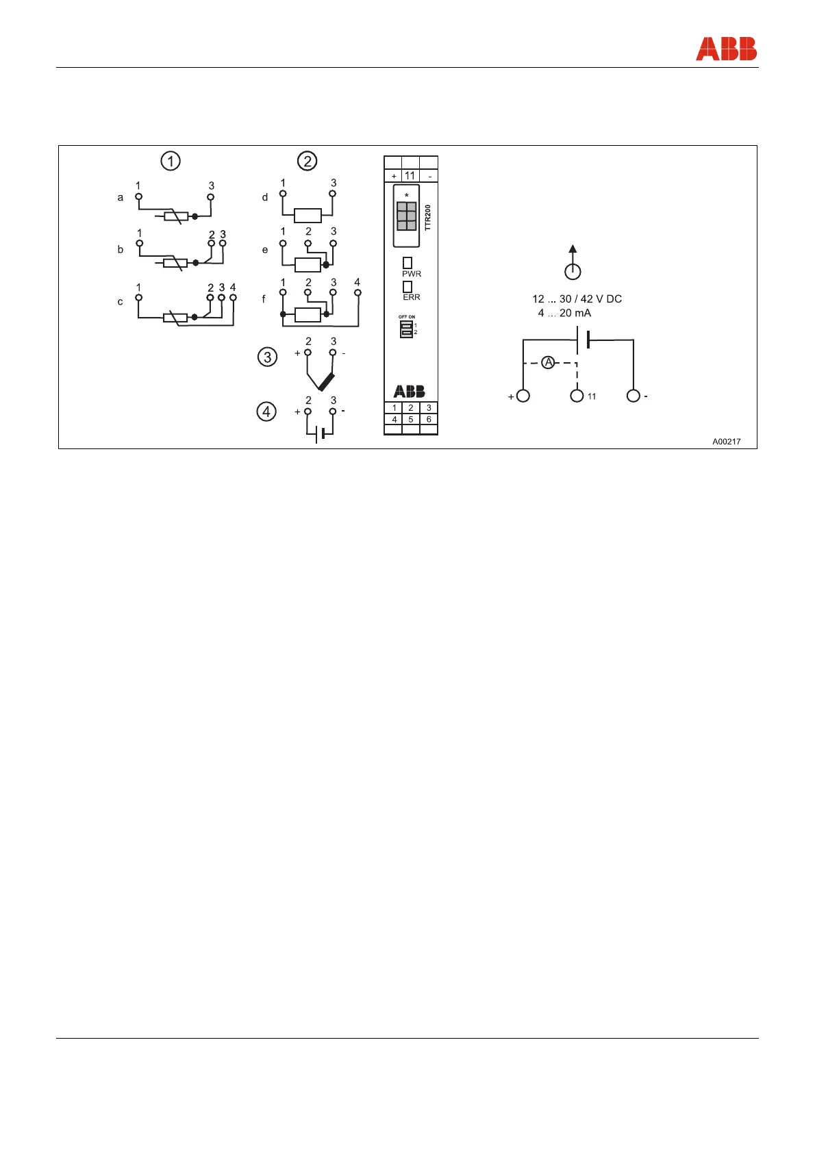
Fig. 3: *(planned local configuration interface/inoperable)
1 Potentiometer: 0 … 500 Ω or 0 … 5000 Ω
a Potentiometer, 2-wire circuit
b Potentiometer, 3-wire circuit
c Potentiometer, 4-wire circuit
2 RTD resistance sensors (e.g., Pt100)
d RTD, 2-wire circuit
e RTD, 3-wire circuit
f RTD, 4-wire circuit
3 Thermocouple
Depending on the sensor model, a variety of line materials can be used
for sensor connections. The integrated reference point makes it possible
to directly connect thermal compensating lines.
4 Voltage measurement
Pos: 14.8 /Elektri scher Anschluss/Temper atur/TTR200/Anmerkun g zu Anschlussplan ( BA) @ 18\mod_1205827740529 _3101.doc @ 170993
Note
Terminal 11: Measurement of 4 … 20 mA output current without opening / interrupting the current loop (see chapter
5.3 Block diagram )
• PWR / green LED: Supply voltage display
• ERR / red LED: sensor, sensor lead & unit fault signaling
• DIP switch 1: on -> Hardware write protection is enabled
• DIP switch 2: no function
Pos: 14.9 /====== = Seitenumbruch ======= = @ 0\mod_1126532365768_3101.doc @ 3830