Electrical connection
OI/TTR200-EN TTR200 15
Pos: 14.10 /Überschri ften/1.1/1-spa ltig/A - C/Blockschal tbild @ 16\mod_1199270222 218_3101.doc @ 147214
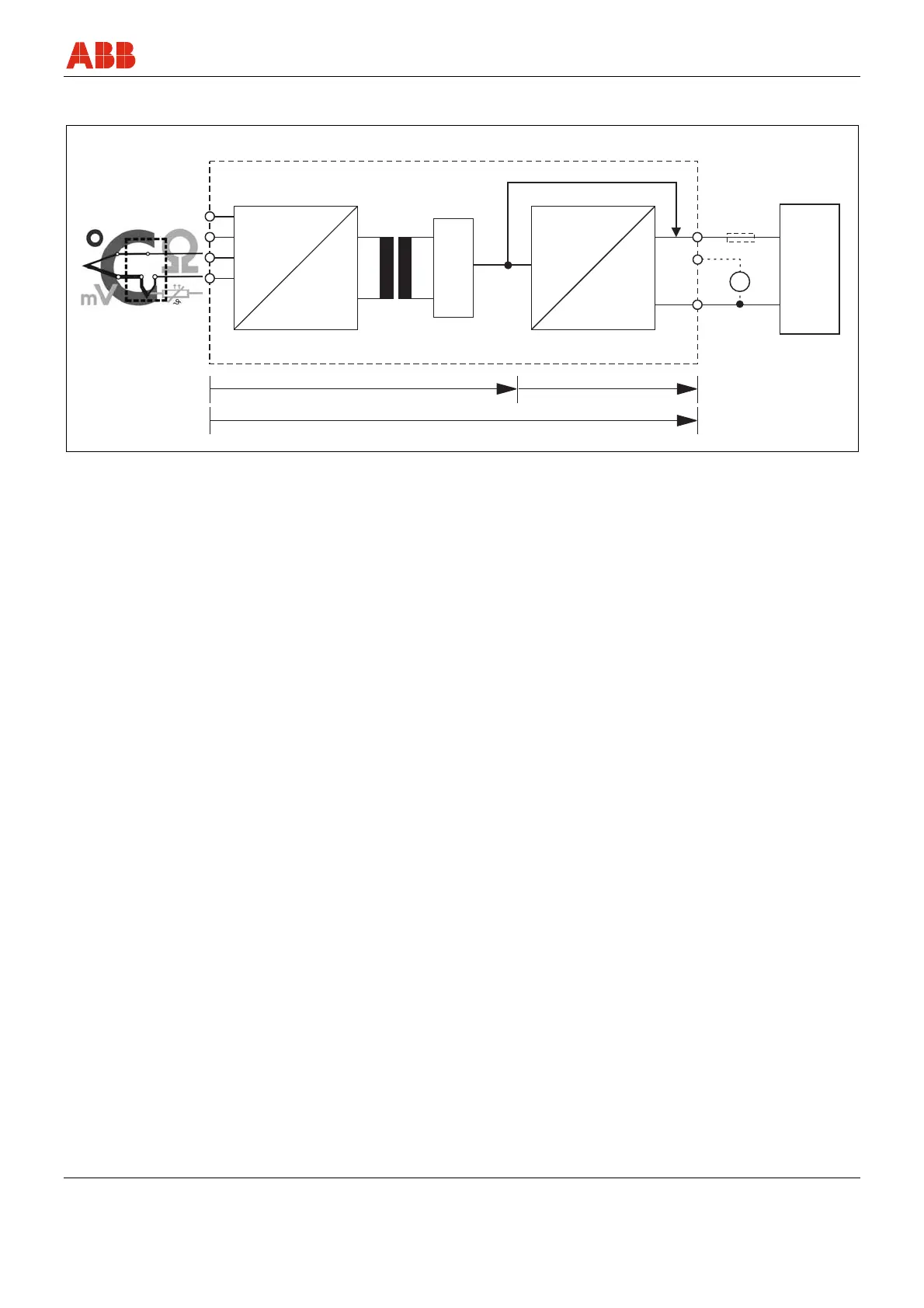
5.3 Block diagram
Pos: 14.11 /Technische Da ten / Datenblatt/ Temperatur/TTR/Techni sche Daten/Blockscha ltbild @ 15\mod_1194870 440921_3101.doc @ 139841
Sensor TTR200 Power supply
A00202
3,5 kV DC
( 2,5 kV AC 60s)~
A
1
2
3
4
-
67
8
D
DA
12 ... 30 (Ex) 42 V DC
min. 12 V DC
5
+
A
9
-
+
Fig. 4
1 24-bit A/D converter
2 Microcontroller
3 16-bit D/A converter
4 HART signal
5 Load (observe voltage drop, refer to the section "Terminal
connection diagrams")
6 Digital measuring accuracy
7 D/A measuring accuracy
8 Overall measuring accuracy
9 Terminal 11, measurement of 4 … 20 mA output current without
opening / interrupting the current loop (internal resistance
ammeter < 15 )
Pos: 14.12 /==== === Seitenumbruch ======= = @ 0\mod_1126532365768_3101.d oc @ 3830