Electrical connection
16 TTR200 OI/TTR200-EN
Pos: 14.13 /Überschri ften/1.1/1-spa ltig/S - U/Standardan wendung @ 16\mod_11980739125 00_3101.doc @ 146614
5.4 Standard application
Pos: 14.14 /Elektri scher Anschluss/Temper atur/TTR200/Signa l-/Versorgungsan schluss Teil 1 @ 16\mod_11981 68131718_3101.doc @ 146748
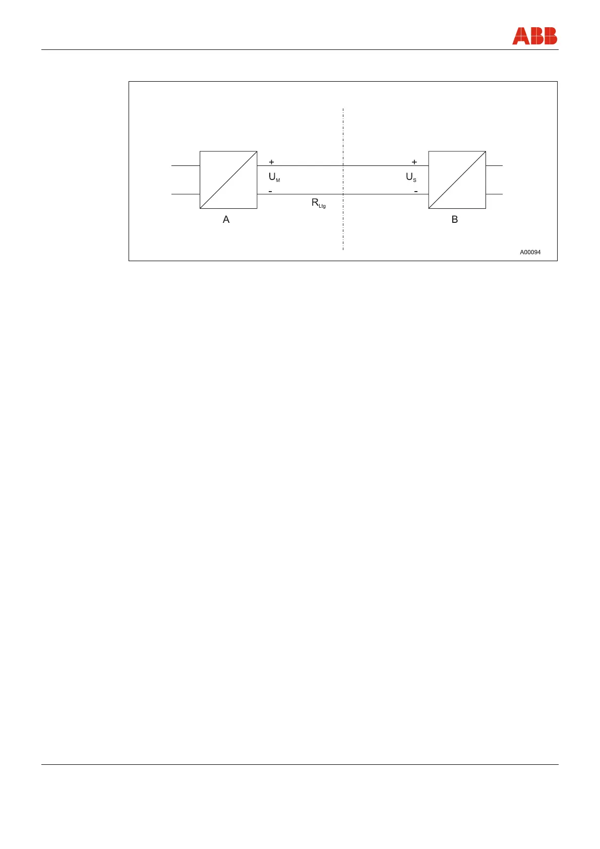
Field Control room
Fig. 5
A Transmitter
B Power supply / SPS input with supply
When connecting transmitters and power supplies, observe the following specification:
U
Mmin
≤ U
Smin
+ 0.02A x R
Ltg
Where
U
Mmin
: Minimum operating voltage of transmitter (refer to technical data for transmitter)
U
Smin
: Minimum supply voltage of repeater power supply / SPS input
R
Ltg
: Line resistance between transmitter and power supply
For HART functionality, use power supplies or SPS input cards with HART mark. If this is not
possible, the interconnection must have a resistance ≥ 250 (< 1100 ).
The signal line can be connected with or without ground. When connecting the ground (minus
side), make sure that only one side of the contact is connected to the equipotential bonding
system.