Connection of the RS485 line
On the inverter models which equip the UNO-DM-COM KIT board (-X
version only) it is possible to use the RS485 communication port for:
Connecting the inverter to an external supported energy meter (to man-
age the energy produced by the PV plant with the Dynamic Feed-in con-
trol functionality); Integrating the inverter with a third party monitoring and
control systems; Carrying out “daisy-chain” (“in-out”) connections of mul-
tiple inverters installation.
The inverter RS458 communication protocol must be properly congured depending on the
device to which it communicates. The RS485 protocol can be changed through the relevant
section of internal webserver (see the specic chapter).
The connection of the serial communication cable must be made to the
specic RS485 connector
26
present on the UNO-DM-COM KIT board.
For connection of the RS485 communication line is necessary a three-
wire shielded cable. The cable specications are described in the fol-
lowing table:
Cable type AWG
Characteristic
impedance
Operating
voltage
Operating
temperature
Shielded 22 - 24 120 Ohm ≥300 V -20...+60 °C
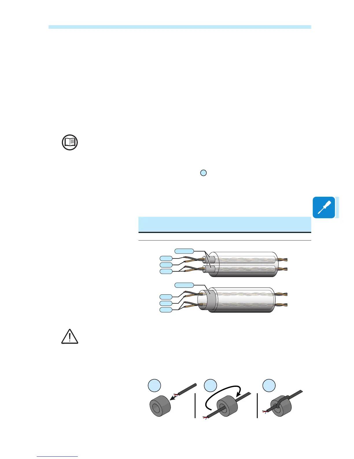
-T/R
+T/R
RTN
-T/R
+T/R
RTN
SHIELD
SHIELD
Shield continuity must be provided along the communication line and must be grounded at a
single point. It is recommended not to exceed a length of 1000m for the communication line.
The cabling of the RS485 line must be winded up to the toroidal provided
in the package (1 winding); this toroidal shall be conveniently placed near
the cable gland which is in the bottom part of the inverter.
1 2 3

 Loading...


