ABB Turbocharger VTC..4 Seite / Page 37
Demontage und Montage Kap. / Chap. 5 Disassembly and assembly
ABB Turbo Systems Ltd
HZTL 10104
- D -
ABB
5.8 Verdichterseitiges Lager einbauen
Vorsicht Nur Originalteile von autorisierten Ser-
vice-Stellen der ABB Turbo Systems
verwenden.
Sicherungs- und Federringe grund-
sätzlich ersetzen.
- Abpressschraube (90040) aus der Abziehvorrich-
tung (90040) entfernen (s. Fig. 5-14).
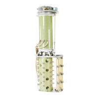
- Kammlager (32001) in die Abzievorrichtung
(90040) einschrauben.
- Mit der Abziehvorrichtung (90040) Kammlager
(32001) vorsichtig bis zur Wellenschulter auf die
Welle schieben.
Vorsicht ! Zur Montage keine Schmiermittel auf
das konische Wellenende auftragen.
Hinweis Stirnseitige Berührungsächen der Ab-
pressschraube und Abziehvorrichtung
mit MOLYKOTE schmieren.
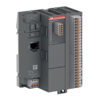
- Abpressschraube (90040) mit der Seite mit durch-
gehendem Gewinde in die Abziehvorrichtung
(90040) montieren.
- Abpressschraube (90040) so weit eindrehen bis
das Kammlager (32001) an der Wellenschulter
ansteht.
- Abziehvorrichtung (90040) und Abpresschraube
(90040) entfernen.
5.8 Installing the compressor
end bearing
Caution ! Use only original spare parts from aut-
horized ABB Turbo Systems service
stations.
Always replace locking rings and was-
hers.
- Remove the puller screw (90040) from the extrac-
tor(90040)(seeg.5-14).
- Screw the thrust bearing (32001) into the extractor
(90040).
- With the extraxtor (90040) carefully slide the thrust
bearing (32001) onto the shaft up to the shaft
shoulder.
Caution ! Do not apply any lubricants on the ta-
pered shaft end.
Note Apply some MOLYKOTE on the contact
surfaces of the puller screw and extrac-
tor.
- Fit the puller screw (90040) with the fully threaded
side into the extractor (90040).
- Screw in the puller screw (90040) until the thrust
bearing (32001) rests on the shaft shoulder.
- Remove the extractor (90040) and the puller screw
(90040).