132 | XSE RIES G5 | 21060 2 6MN AA
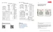
Figure 11-4: XRC
G5
AIs
Figure 11-5: XRC
G5
AIs and mode selector jumpers (default setting)
To set the AI to voltage mode:
If calibrating on the XFC: AIs support voltage mode by default. Ensure that there are no
external resistors connected across the AI pins.
If calibrating on the XRC: Verify that the mode selector jumper (J21, J22, J24, J25 or J26)
is across pins 2 and 3 for the selected AI.
To set the AI to current mode:
If calibrating on the XFC: Insert a precision resistor across the selected AI pins.
If calibrating on the XRC: Place the mode selector jumper (J21, J22, J24, J25 or J26)
across pins 1 and 2 for the selected AI.
11.5.3 Analog input calibration (voltage mode)
This procedure describes a three (3) point calibration. Available target values for this option display in
the calibration window and become active in calibration order:
Low Cal Point
100% Cal Point
50% Cal Point
These instructions can be adapted for a five (5) point calibration. The five pressure points display in
calibration order:
Low Cal Point
100% Cal Point
75% Cal Point
50% Cal Point
25% Cal Point