| Installation – Electrical connection of the wallbox
18
Proceed as follows to connect the power supply cable inside the wallbox:
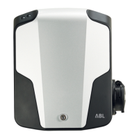
1 Cut the supply cable to the required length with the
pliers/wire stripper.
y For wiring up group installations (see next
section), you must also cut the data cables to the
required length.
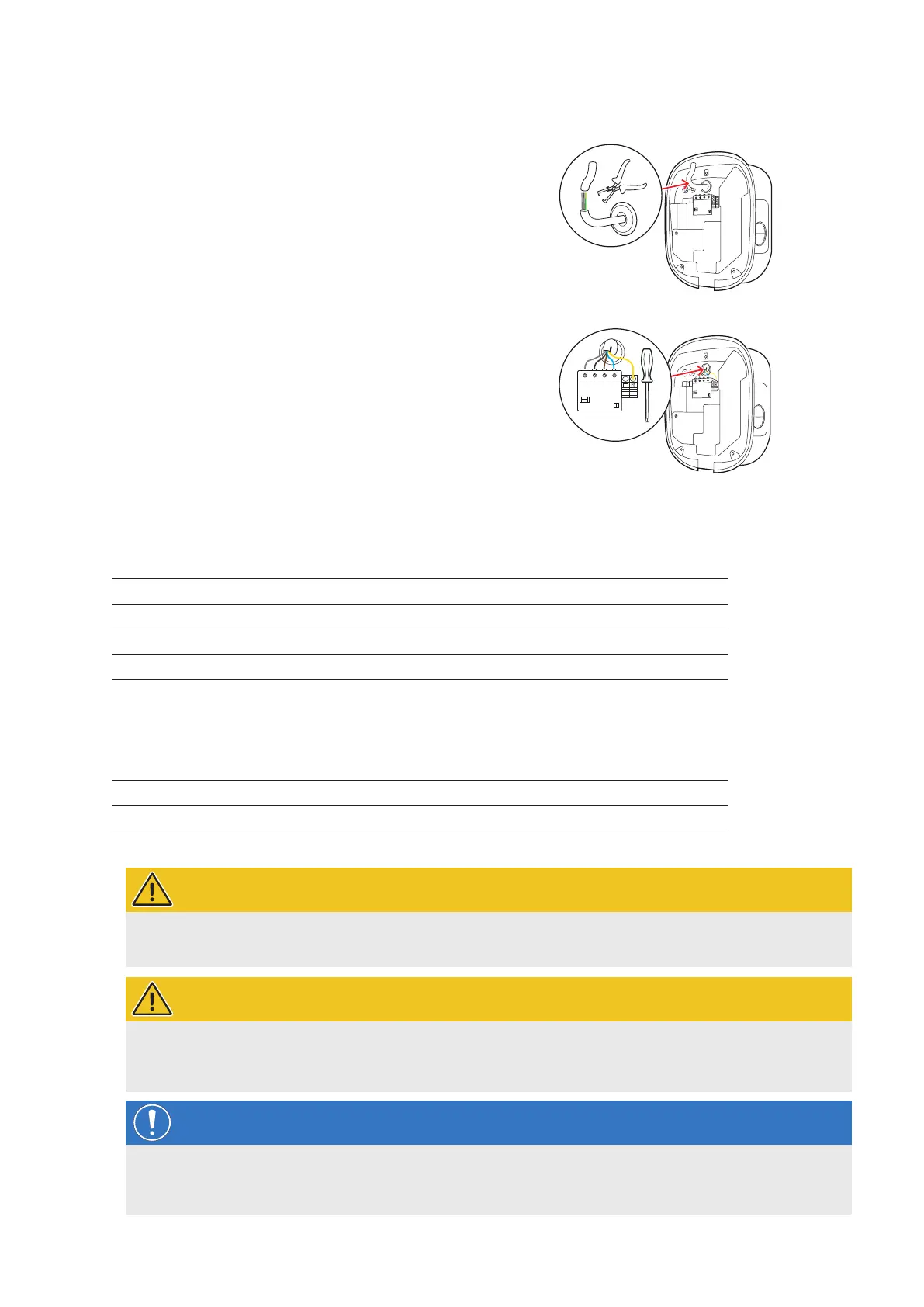
2 Insert the individual conductors of the power supply ca-
ble into the respective terminals of the RCCB and tight-
en them using the screwdriver (torque: 2.5 to 3Nm).
y End ferrules must be fitted on flexible conductors.
y Operate the spring-loaded mechanism of the
PE terminal and attach the protective earth
conductor.
y Use the connection patterns listed below to allo-
cate the individual conductors.
Connection pattern for 3-phase TN system
Designation Conductor colour Marks for
Phase 1 current-carrying conductor Brown
5 – L1
Phase 2 current-carrying conductor Black
3 – L2
Phase 3 current-carrying conductor Grey
1 – L3
Neutral Blue N
Protective earth Green-Yellow PE
Connection pattern for 1-phase TN system
Designation Conductor colour Marks for
Phase 1 current-carrying conductor Brown
5 – L1
Neutral Blue N
Protective earth Green-Yellow PE
WARNING!
Allocation of wire colours
Please note that the colour-coding convention used above is not internationally standardised.
WARNING!
Checking the connection
Please ensure that the conductors that are pre-fixed to the RCCB terminals remain attached correctly after con-
necting the power supply cable.
NOTE
Single-phase operation of the Wallbox eMH2
If desired, the 3-phase Wallbox eMH2 model variant can also be connected and operated on a single phase at
terminal 5 – L1: However, in this case the rated output for the wallbox will not be achieved.
 Loading...