Ma in t e nan c e | Exch a ng i ng t h e c h ain a nd c h ai n s p r o ck e t
46
ONLY WITH AN ELECTRONIC
HOIST LIMIT SWITCH
This work step is only applicable if the hoist limit
switch PCB is visible in the housing:
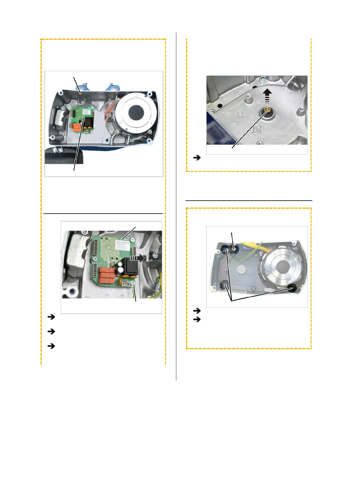
Housing
Hoist limit switch PCB
REMOVING THE HOIST LIMIT
SWITCH
Hoist limit switch PCB
Fillister-head screws with
ribs M5x10
Pull the connector off the hoist limit switch
PCB.
Unscrew the fillister-head screws with ribs
M5x10 (3x).
Take the hoist limit switch PCB out of the
chain hoist.
The magnet carrier of the hoist limit switch is firmly
screwed to the output shaft of the gear unit. It must
be unscrewed as otherwise it would damage
components when the gear unit is pulled off.
Magnet carrier
Unscrew the magnet carrier.
TAKING OUT THE CHAIN GUIDE
ONLY FOR GM2
Locking screw
Fillister-head screws
Unscrew the fillister-head screws (3x).
Leave the locking screw tightened.
It later ensures that the gear unit cannot not
fall down.