Ma in t e nan c e | Sett i n g t h e air g a p o n t h e bra k e
69
CONCLUDING THE SETTING OF THE
AIR GAP
Screw in the banjo bolts (3x) in the direction of
the travel motor until hand-tight.
Tighten the hexagon head screws (3x).
Size Size and length Tightening torque
GM2 M4x45 3 Nm
GM4 M5x55 6 Nm
GM6 M6x65 10 Nm
GM8 M6x65 10 Nm
● The brake is fixed with screws.
Check the air gap next to all three hexagon
head screws. If different than the set width,
repeat the adjustment.
COVERING THE BRAKE
Dust guard ring
Pull the dust guard ring over the brake.
CONNECTING THE CHAIN HOIST
Attach the couplings of the hoist motor and
brake to the pin multipoint connectors of the
control in the motor cover.
Only connect couplings and pin multipoint
connectors of identical colour (orange and
grey).
For the assignment, see “Wiring diagrams”,
page 93.
With electronic hoist limit switch: Insert the
connector on the hoist limit switch PCB.
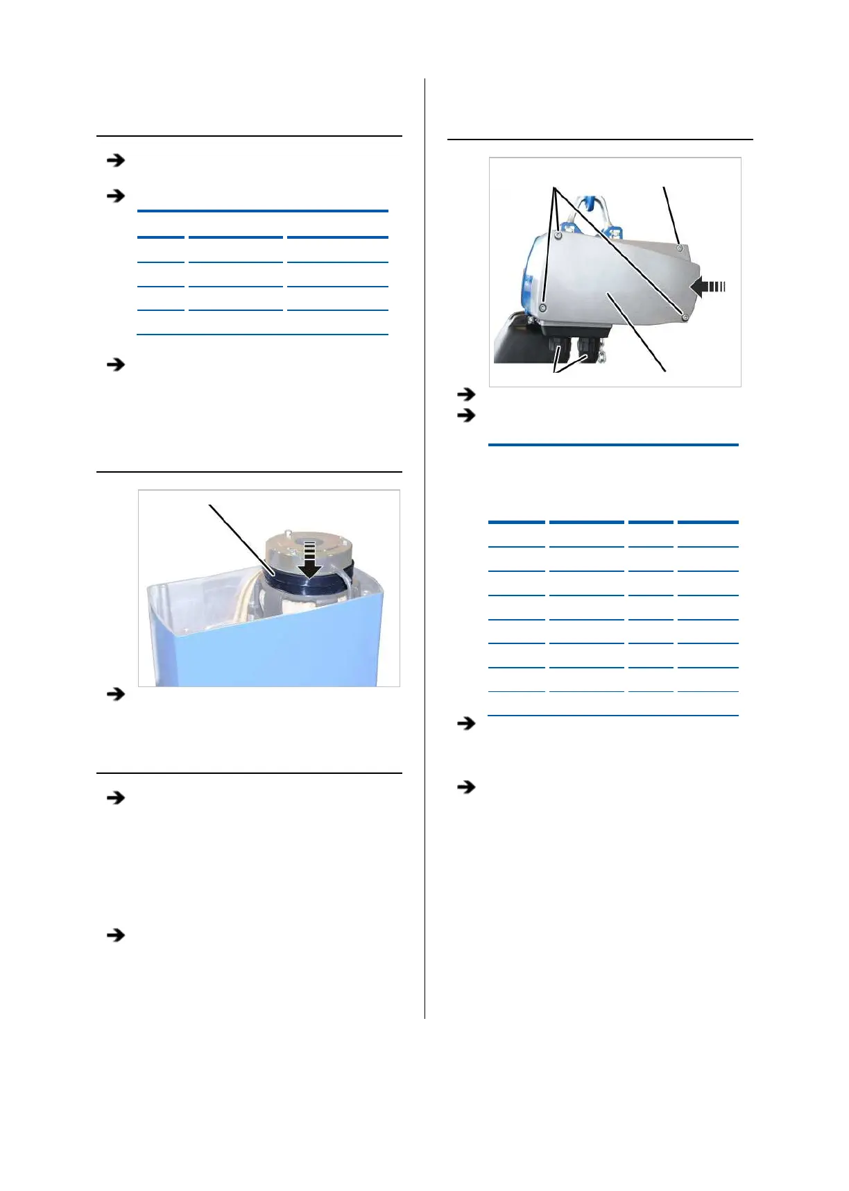
CLOSING THE CHAIN HOIST
Long fillister-head
screws
Short fillister-head
screw
Bayonet coupling Motor cover
Hold the motor cover on the housing.
Note the different screw lengths and screw in
the fillister-head screws.
Size
Size and
length
Number
Tightening
torque
GM2 M5x65 3x 4 Nm
GM2 M5x45 1x 4 Nm
GM4 M5x60 3x 4 Nm
GM4 M5x50 1x 4 Nm
GM6 M8x110 3x 15 Nm
GM6 M8x60 1x 15 Nm
GM8 M10x95 3x 20 Nm
GM8 M10x50 1x 20 Nm
Insert the bayonet coupling of the connection
cable and the bayonet connector of the control
cable. Due to a notch, the plug-in connections
will only fit together in one position.
Slide on and tighten the bayonet nuts.