Ma in t e nan c e | Sett i n g t h e air g a p o n t h e bra k e
68
REMOVING THE CHAIN BOX
Bolt
Chain box
Release the SL safety clip(s) (1x or 2x) from
the bolt.
Hold the chain box firmly and pull out the
bolt(s) (1x or 2x).
Remove the chain box.
OPENING THE CHAIN HOIST
Bayonet nut Motor cover
Release the bayonet nuts.
Detach the connection cable and control cable.
Unscrew the motor cover from the housing.
● The fillister-head screws are secured by O-
rings and thus do not fall out of the motor
cover.
Detach the couplings of the hoist motor and
brake from the control in the motor cover.
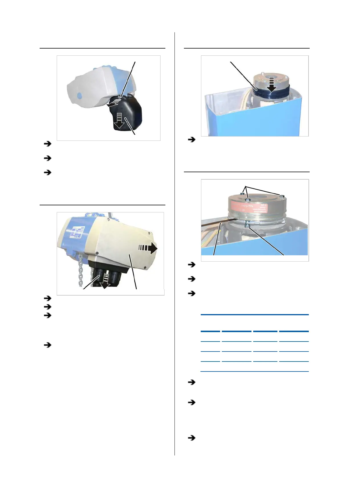
UNCOVERING THE BRAKE
Dust guard ring
Pull off the dust guard ring.
SETTING THE AIR GAP
Hexagon head screws
Feeler gauge Banjo bolts
Unscrew the hexagon head screws (3x) by a
half turn.
Screw in the banjo bolts (3x) by a half turn in
the direction of the magnet body.
Read off the set width of the air gap from the
table.
Size Air gap
target value
air gap
gap
GM2 0.25 mm 0.6 mm 0.2 mm
GM4 0.3 mm 0.6 mm 0.2 mm
GM6 0.35 mm 0.6 mm 0.3 mm
GM8 0.35 mm 0.6 mm 0.3 mm
Insert the appropriate feeler gauge directly next
to one of the hexagon head screws in the air
gap between magnet body and anchor plate.
Tighten the hexagon head screws so that the
feeler gauge can still be pulled from the air
gap.
● The air gap on this hexagon head screw is now
adjusted to the set width.
Repeat the steps for all hexagon head screws
(3x).