Ma in t e nan c e | Sett i n g t h e air g a p o n t h e bra k e
67
ASSEMBLING THE BOTTOM BLOCK
Lay the bottom block halves flush against
one another.
Tighten the fillister-head screws (2x) with
self-locking nuts.
Size Size and
length
Tightening
torque
GM2 M6x30 10 Nm
GM4 M8x35 25 Nm
GM6 M10x45 36 Nm
GM8 M12x75 49 Nm
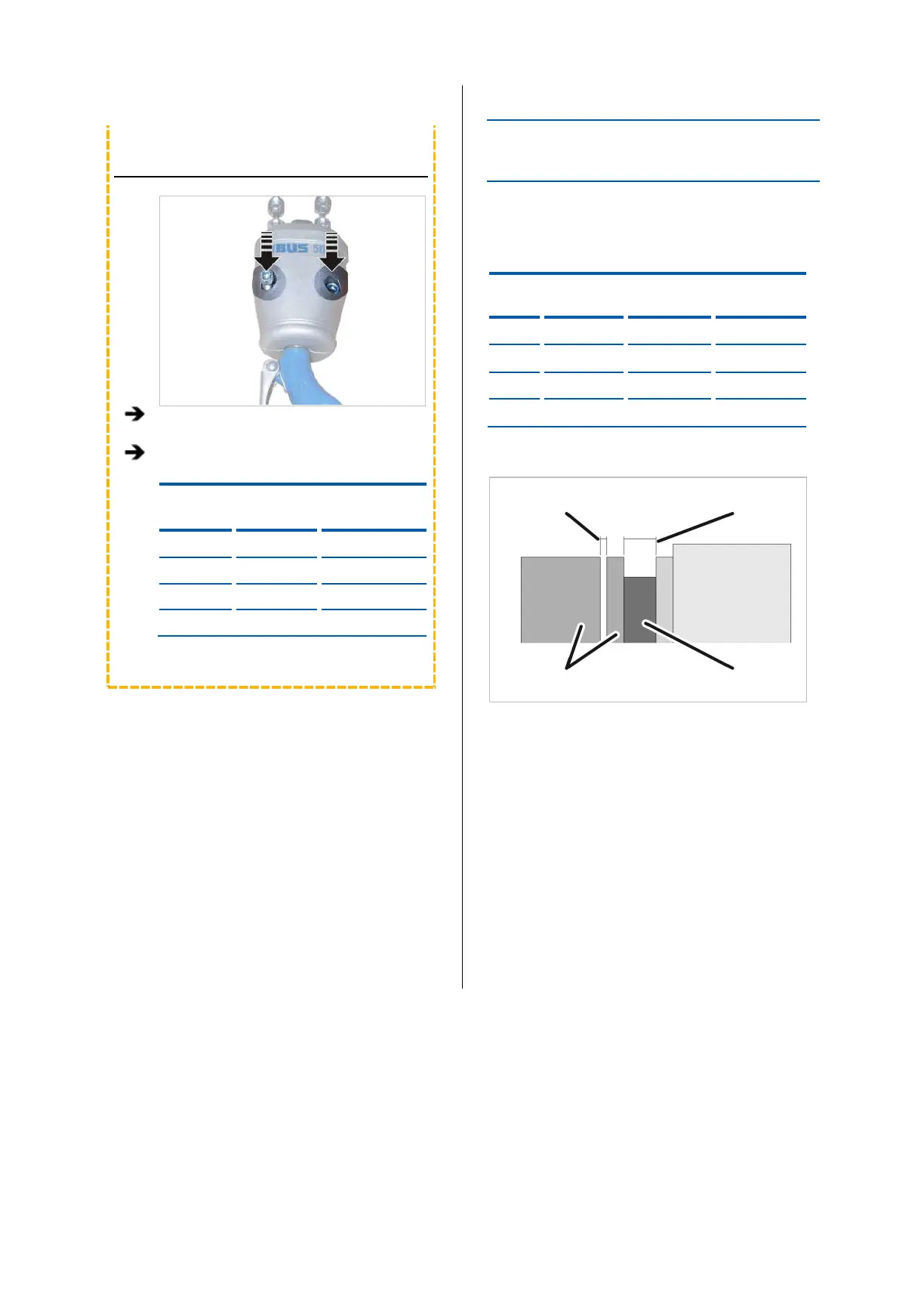
SETTING THE AIR GAP ON THE
BRAKE
If the air gap is wider than permitted, it must be
readjusted.
Overview:
Size Air gap
target value
gap
Minimum air
gap
GM2 0.25 mm 0.6 mm 0.2 mm
GM4 0.3 mm 0.6 mm 0.2 mm
GM6 0.35 mm 0.6 mm 0.3 mm
GM8 0.35 mm 0.6 mm 0.3 mm
Air gap (between magnet
body and anchor plate) Brake lining thickness
Magnet body and anchor
plate
Brake rotor with brake
lining
As soon as the chain hoist stops running, the anchor
plate presses against the brake rotor by spring force,
braking the motor. An air gap is created between the
magnet body and the anchor plate. When the chain
hoist starts up, the magnetic body pulls the anchor
plate away from the brake rotor and the motor can
rotate freely again.
If the brake lining is worn, the air gap will be larger.
See “Checking the brake on the chain hoist”, page 36.
If the air gap is larger than the maximum permitted,
the brake must be readjusted. If the brake lining on
the brake rotor is worn too thin, it must be replaced.
See “Replacing the brake rotor ”, page 71.