Notes:
If the unit is turned off while the blow function is activated, the indoor fan will run at low speed for 2 minutes with the word “BLOW”
displayed on the LCD.
Blow function is not available in FAN or HEAT mode.
3.11 Other Functions
a. Lock
While the unit is OFF, press or at the same time for 5 seconds on the remote controller. Doing so will enable lock mode and
a icon will appear on the LCD. To unlock, press these two buttons simultaneously for 5 seconds. While the unit is locked, no
response will be gained by pressing any other combination of buttons.
b. Memory
While the unit is OFF, press the MODE and buttons simultaneously for 5 seconds to switch between memory ON and
memory OFF. Once activated, memory will be displayed. Memory allows the user to set the following; ON/OFF, Set Temperature,
Mode, Set Fan Speed and Lock Function.
4. Installation and Dismantlement
4.1 Connection of the Signal Line of the Wired Controller
• Open the cover of the electric control box on the indoor unit.
• Place the single line of the wired controller through the rubber ring.
• Connect the signal line of the wired control to the 4-pin socket of the indoor unit PCB.
• Tighten signal wire with zip ties.
• Communication distance between the main board and the wired controller can be up to 66 feet. Standard distance is 24 feet.
4.2 Installation of the Wired Controller
67
Installation and Maintenance
Service Manual
Notes:
(1)When the Blow function is activated, if turning off the unit by pressing On/Off or by the remote controller, the indoor fan will run at the
low fan speed for 2 min, with “BLOW” displayed on the LCD. While, if the Blow function is deactivated, the indoor fan will be turned off
directly.
(2)Blow function is unavailable in the Fan or Heating mode.
3.11 Other Functions
a. Lock
Upon startup of the unit without malfunction or under the “Off” state of the unit, press ▲ and ▼ at the same time for 5s till the wired
controller enters the Lock function. In this case, LCD displays
.
After that, repress these two buttons at the same time for 5s to quit this function.
Under the Lock state, any other button press wont get any response.
b. Memory
Memory switchover: Under the “Off” state of the unit, press Mode and ▲ at the same time for 5s to switch memory states between
memory on and memory off. When this function is activated, Memory will be displayed. If this function is not set, the unit will be under the
“Off” state after power failure and then power recovery.
Memory recovery: If this function has been set for the wired controller, the wired controller after power failure will resume its original
running state upon power recovery. Memory contents: On/Off, Mode, set temperature, set fan speed and Lock function.
4. Installation and Dismantlement
4.1 Connection of the Signal Line of the Wired Controller
● Open the cover of the electric control box of the indoor unit.
● Let the single line of the wired controller through the rubber ring.
● Connect the signal line of the wired control to the 4-pin socket of the indoor unit PCB.
● Tighten the signal wire with ties.
● The communication distance between the main board and the wired controller can be up to 20 meters ( the standard distance is 8
meters)
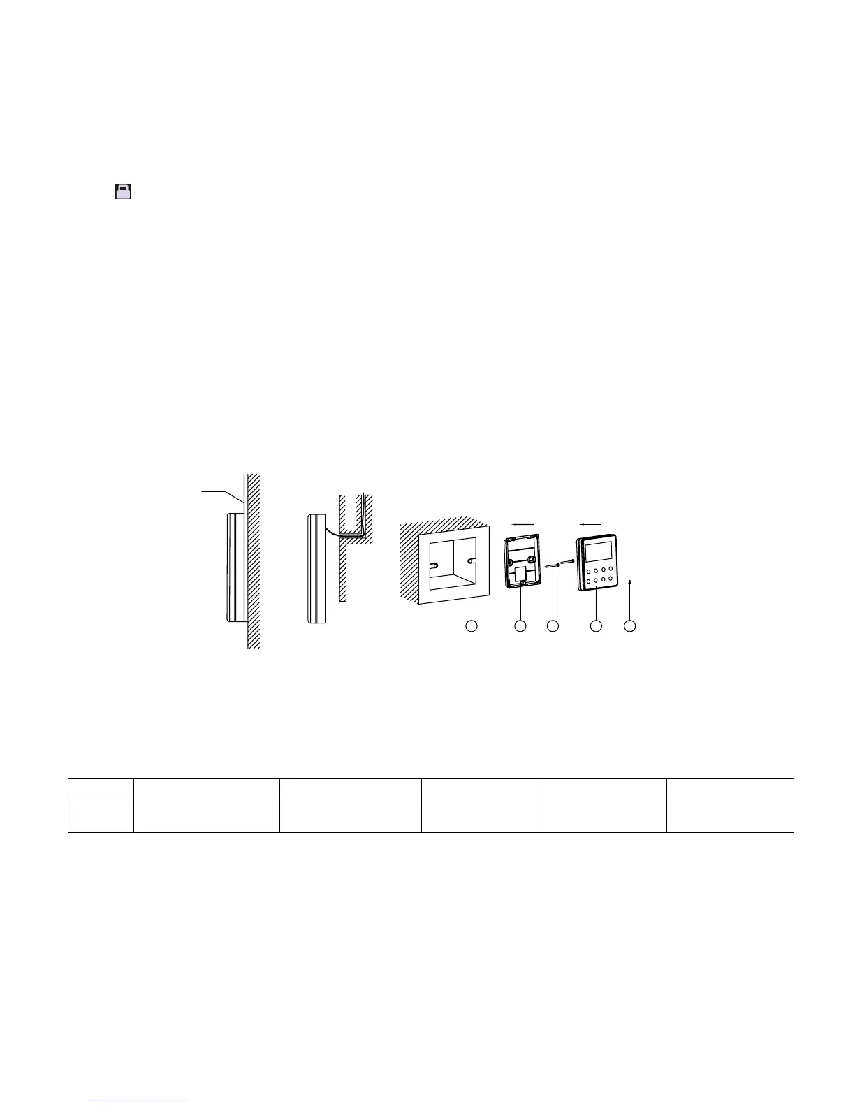
4.2 Installation of the Wired Controller
1
3 4 52
Fig.4.1 Accessories for the Installation of the Wired Controller
No. 1 2 3 4 5
Name
Socket box embedded
in the wall
Soleplate of the Wired
Controller
Screw M4X25
Front Panel of the
Wired Controller
Screw ST 2.9X6
67
Installation and Maintenance
Service Manual
Notes:
(1)When the Blow function is activated, if turning off the unit by pressing On/Off or by the remote controller, the indoor fan will run at the
low fan speed for 2 min, with “BLOW” displayed on the LCD. While, if the Blow function is deactivated, the indoor fan will be turned off
directly.
(2)Blow function is unavailable in the Fan or Heating mode.
3.11 Other Functions
a. Lock
Upon startup of the unit without malfunction or under the “Off” state of the unit, press ▲ and ▼ at the same time for 5s till the wired
controller enters the Lock function. In this case, LCD displays .
After that, repress these two buttons at the same time for 5s to quit this function.
Under the Lock state, any other button press wont get any response.
b. Memory
Memory switchover: Under the “Off” state of the unit, press Mode and ▲ at the same time for 5s to switch memory states between
memory on and memory off. When this function is activated, Memory will be displayed. If this function is not set, the unit will be under the
“Off” state after power failure and then power recovery.
Memory recovery: If this function has been set for the wired controller, the wired controller after power failure will resume its original
running state upon power recovery. Memory contents: On/Off, Mode, set temperature, set fan speed and Lock function.
4. Installation and Dismantlement
4.1 Connection of the Signal Line of the Wired Controller
● Open the cover of the electric control box of the indoor unit.
● Let the single line of the wired controller through the rubber ring.
● Connect the signal line of the wired control to the 4-pin socket of the indoor unit PCB.
● Tighten the signal wire with ties.
● The communication distance between the main board and the wired controller can be up to 20 meters ( the standard distance is 8
meters)
4.2 Installation of the Wired Controller
1
3 4 52
Fig.4.1 Accessories for the Installation of the Wired Controller
No. 1 2 3 4 5
Name
Socket box embedded
in the wall
Soleplate of the Wired
Controller
Screw M4X25
Front Panel of the
Wired Controller
Screw ST 2.9X6
No. 1 2 3 4 5
Name
Socket box embedded
in the wall
Soleplate of the
Wired Controller
Screw M4X25
Front Panel of the
Wired Controller
Screw ST 2.9X6