REMOVAL PROCEDURE
Removal Procedure of Indoor Unit
Step Procedure
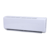
1. Remove filter assembly
Open the front panel. Push the left filter
and right filter until they are separate from
the groove on the front panel.
Remove the left filter and right filter
respectively.
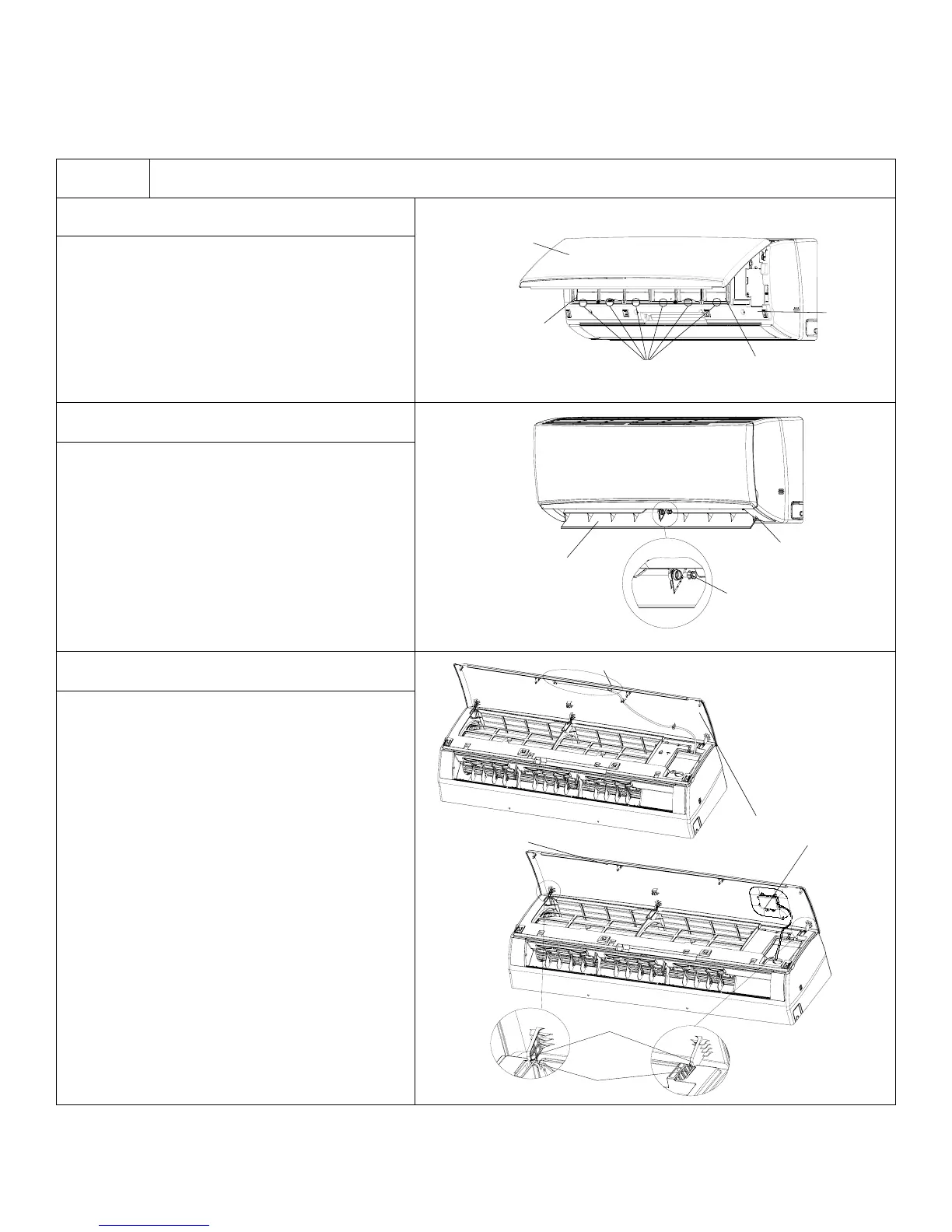
2. Remove horizontal louver
Push out the axile bush on horizontal
louver. Bend the horizontal louver by
hand and separate the horizontal
louver from the crankshaft of step motor
to remove it.
3. Remove panel and display
a. A1/A5 panel display: Remove the 2
screws that are locking display board.
Separate display board from front panel.
b. B2/A5/D5 display: Remove the 2 screws
that are locking the display board.
Separate panel rotation shaft from
groove fixing on the front panel and
remove the front panel.
Warning: Be sure to wait for a minimum of 20 minutes
after turning off all power supplies and discharge the
refrigerant completely before removal.
91
Installation and Maintenance
Service Manual
11. Removal Procedure
11.1 Removal Procedure of Indoor Unit
Warning: Be sure to wait for a minimum of 20 minutes
after turning off all power supplies and discharge the
refrigerant completely before removal.
a
b
Axile bush
Push out the axile bush on horizontal
louver. Bend the horizontal louver with
hand and then separate the horizontal
louver from the crankshaft of step motor
to remove it.
Horizontal louver
Location of step motor
ProcedureStep
1. Remove lter assembly
NOTE: Take A5 panel for an example.
2. Remove horizontal louver
Front panel
Front
case
Right lter
Groove
Left lter
Open the front panel. Push the left lter
and right lter until they are separate from
the groove on the front panel.
Remove the left lter and right lter
respectively.
(1)A1 display: Screw off the 2 screws that
are locking the display board. Separate
the display board from the front panel.
(2)A3/A5 display: Screw off the 2 screws
that are locking the display board.
Separate the panel rotation shaft from
the groove xing the front panel and then
removes the front panel.
3. Remove panel
Panel
Screws
Screws
Screws
A1 display
A5 display
A3 display
Front panel
Panel rotation
Groove
127
Installation and Maintenance
Service Manual
11. Removal Procedure
11.1 Removal Procedure of Indoor Unit
Warning: Be sure to wait for a minimum of 20 minutes
after turning off all power supplies and discharge the
refrigerant completely before removal.
a
b
Axile bush
Push out the axile bush on horizontal
louver. Bend the horizontal louver with
hand and then separate the horizontal
louver from the crankshaft of step motor
to remove it.
Horizontal louver
Location of step motor
ProcedureStep
1. Remove lter assembly
2. Remove horizontal louver
Front panel
Front
case
Right lter
Groove
Left lter
Open the front panel. Push the left lter
and right lter until they are separate from
the groove on the front panel.
Remove the left lter and right lter
respectively.
(1)A1/A5 panel display: Screw off the 2
screws that are locking the display board.
Separate the display board from the front
panel.
(2)B2/A5/D2 panel display: Screw off
the 2 screws that are locking the display
board.
Separate the panel rotation shaft from
the groove xing the front panel and then
removes the front panel.
3. Remove panel and display
A5/B2/D2 display
Front panel
Panel rotation
Groove
Panel
A1/A5/B6 display