13
4-20mA Outputs 1 and 2
The 4-20mA output terminals provide an internally-powered 4mA to 20mA converter that generates a current output
proportional to the measured temperature on either TC1, TC2, or TC3 (selectable via the menu system). An option in the menu
system allows users to select the output mode: either a direct current output directly proportional to temperature, a proportional
valve output that slowly controls an external 4-20mA valve around the selected setpoint temperature (plus or minus 5 degrees
window), or it can output either of the 4-20mA Input readings (emulating a "splitter" mode). The "splitter" mode allows for
this output to re-broadcast one of the 4-20mA Input readings to an external PLC. See the "4-20mA Output Connection
Notes for Rev 1D CSC400 boards" section for additional details in wiring these connections.
Notes:
- An output of 3.5mA means there's an error. This could mean that the selected thermocouple for the 4-20mA Output is
disabled.
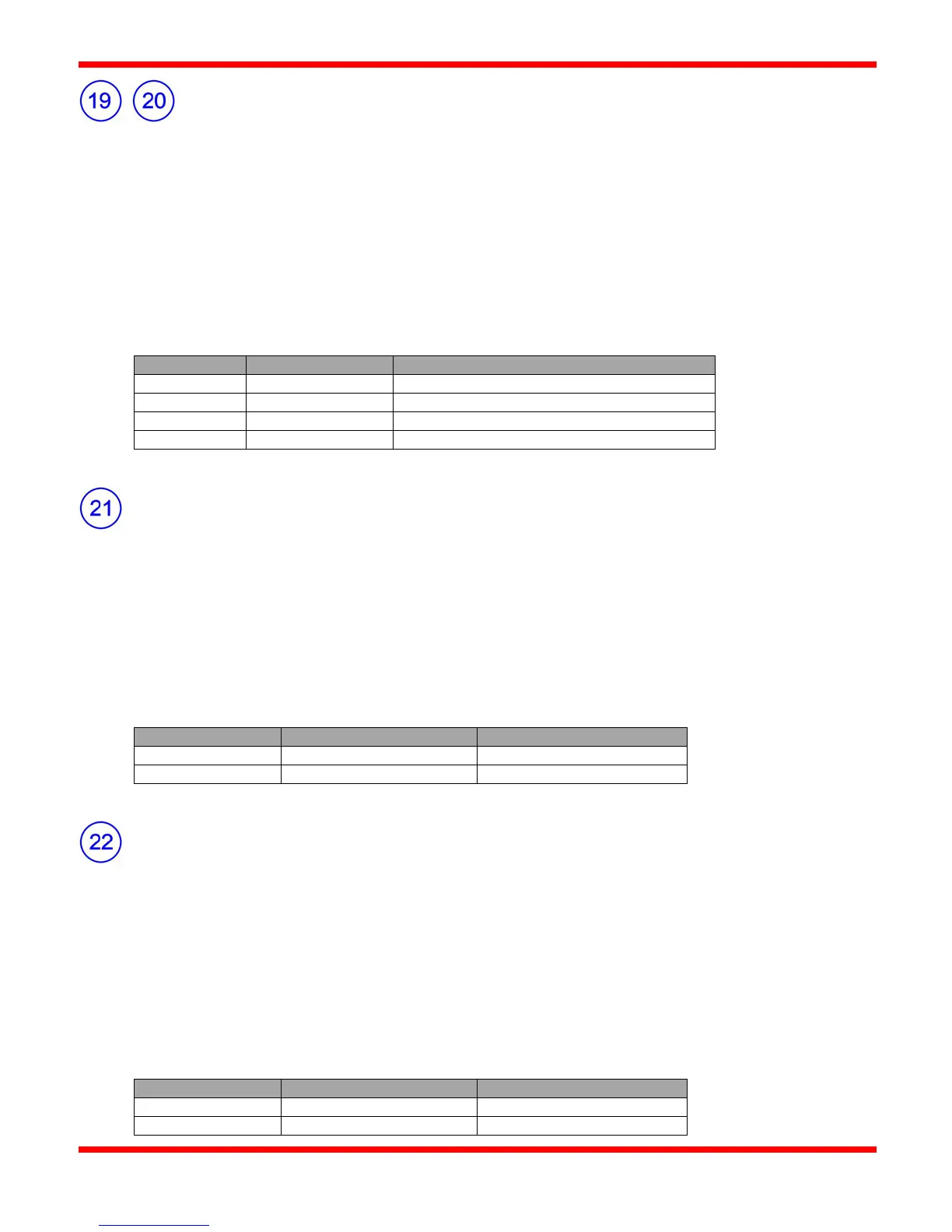
4-20mA Output 1 (mA Out) +
4-20mA Output 1 (TX) (GND) -
4-20mA Output 2 (mA Out) +
4-20mA Output 2 (I/P) (GND) -
Proof of Closure Input
The Proof of Closure Input terminals are used when a proof of closure safety shutdown valve is used in a system. If the POC
switch is open, it prevents power from being delivered to the ignition module. This safety feature eliminates the risk of
igniting a burner if the POC valve is partially open and the proof of closure switch indicates open. This is also a failsafe input
as it will not allow ignition to initiate if a wire is broken or disconnected.
These terminals must be wired to dry contacts of a remote Proof of Closure switch when used. A wire jumper must remain
across the Proof of Closure terminals when not in use.
The CSC400 LED display will flash "POC" when the Proof of Closure input is open.
Remote Start/Stop Input
The Remote Start/Stop input allows the user to hard wire a remote switch or relay for controlling the CSC400. These terminals
must be wired to dry contacts of a remote switch or relay when used. The Remote Start/Stop switch turns on and off the power
delivered to the ignition modules as long as all other shutdowns and Proof of Closure inputs are closed and temperature values
for TC1 & TC2 (if enabled) thermocouples are within the allowable range. A wire jumper must remain across the Remote
Start/Stop terminals when not in use.
The CSC400 must have been started already for the Remote Start/Stop Input to function. The CSC400 is started by pressing
the Start button locally, or by receiving a Modbus Remote Start command.
The CSC400 LED display will show "RemStop" when the Remote Start/Stop input is open.