12
The VDCIN - (negative) terminal is connected to ground internally on the CSC400 printed circuit board.
The Main power inputs (VDCIN + and VDCIN -) are protected against reverse polarity. The CSC400 will not operate if the
Main Power Input wires are reversed and it will not cause damage to the CSC400 electronics.
Bonding Ground Inputs
Extra system bonding ground terminal connections are provided.
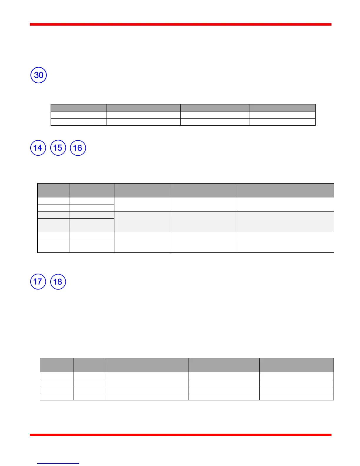
Thermocouple 1, 2, and 3 Inputs ("T/C1", "T/C2", "T/C 3")
The CSC400 controller accepts three type-K (ungrounded) thermocouples. They are clearly marked on the board for each
thermocouple and polarity (See wiring diagram "Figure 8 - CSC400 Wiring Diagram" on page 23).
(-76°F to 2192°F)
Process temperature measurements
and solenoid control
(-76°F to 2192°F)
recommended for use as
High-temperature shutdown for IGN1
and IGN2
(-76°F to 2192°F)
May be used for process temperature
measurements, 4-20 Output control, or
as an auxiliary high-temp shutdown
The temperature range for each thermocouple is -60°C to 1200°C (-76°F to 2192°F).
4-20mA Level / Pressure / Temperature Inputs
The 4-20mA input terminals provide a powered 4mA to 20mA (or 1V to 5V) converter that reads a current (or voltage) input
from an external transmitter. The 4-20mA Inputs can be configured to simply provide a scaled measurement of the external
transmitter, or they can be configured to shutdown the burners if either 4-20mA input reads a value above the High Trip-point,
or below the Low Trip-point. An "Alarm only" or "Shutdown on Alarm" option is provided for each input ("SD on Alarm
Yes/No") in case the user wishes to alarm but not shut down the burners on a Low and/or High reading. The 4-20mA Inputs
may also be used with 4-20mA transmitters for setpoint control of either or both burner outputs. An OR-ing scheme is used if
both 4-20mA Inputs use setpoint control on the same burner. See the "4-20mA Input Connection Notes for Rev 1D
CSC400 Boards" section for additional details in wiring these connections.
Output Source for 4-20mA
Inputs
4-20mA Level Input (1) "-"
4-20mA Pressure Input (2) "-"