15
ignition module as long as all other shutdowns and Proof of Closure inputs are closed and temperature values for both
thermocouples are within the allowable range. A wire jumper must remain across the Shutdown terminals when not in use.
The CSC400 LED display will show "Aux 1" when the Auxiliary Shutdown 1 input is open.
The CSC400 LED display will show "Aux 2" when the Auxiliary Shutdown 2 input is open.
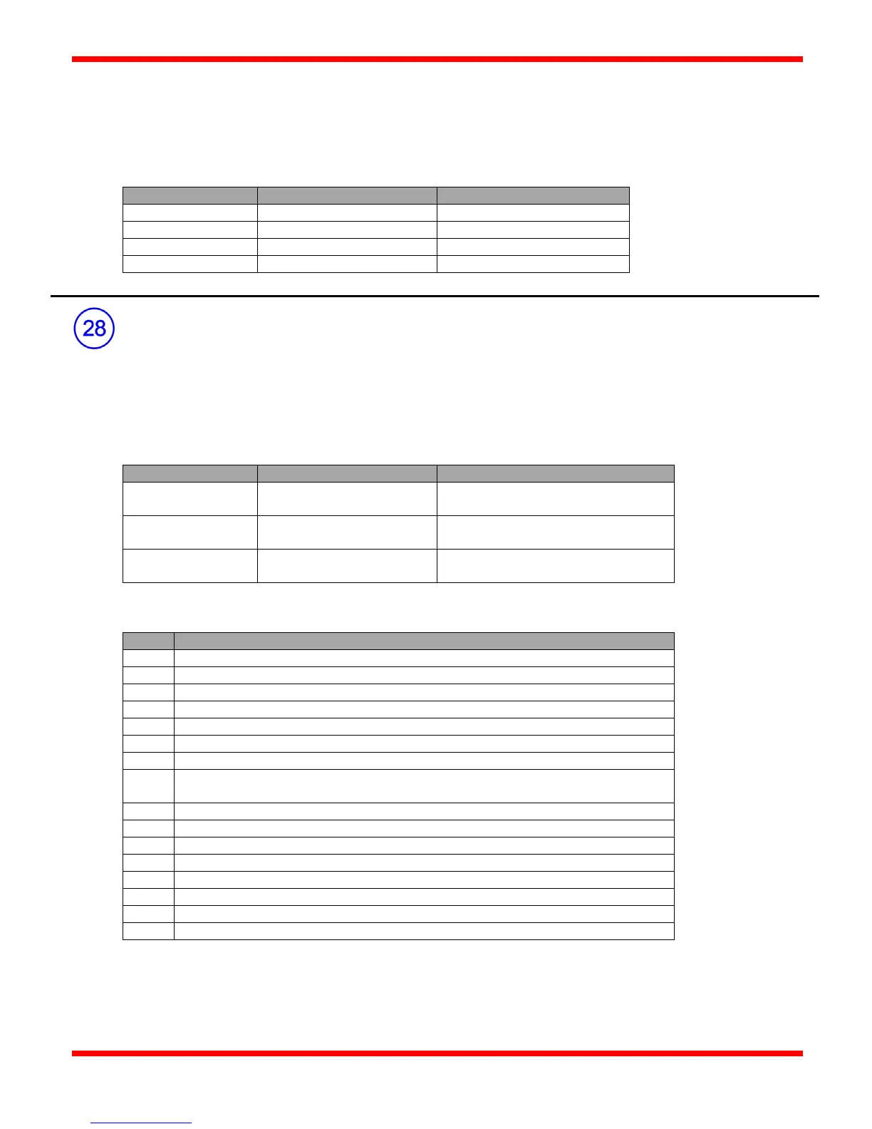
Alarm Status Output
The Alarm Status output provides remote indication of an Alarm condition on the CSC400. When power to the CSC400 is off,
the Alarm Status contacts are open between "NO" and "COM" and closed between "NC" and "COM", indicating an Alarm
condition. The contacts are also in an Alarm condition when the CSC400 is in a shutdown state. Eg: a Shutdown switch or the
Remote Start/Stop switch is open. This provides a complete fail-safe indicator to a remote control center of the status of the
CSC400 controller.
rms
DC
rms
DC
Voltage: 30VDC, 30V
(AC)
rms
DC
Possible Alarm Conditions
Remote Start/Stop switch is open
High Temperature shutdown (Thermocouple 2)
High-Temp Latch condition
Shutdown switch is open (High Gas, Low Gas, Level, Aux 1, Aux 2)
Proof of Closure valve is open
Shutdown Latch condition (High Temp, High Gas, Low Gas, Level, Aux 1, Aux 2,
4-20mA Input)
Power Fail Latch condition
Short detected on solenoid valve output terminals
4-20mA Input Lo/Hi Shutdown enabled
Modbus Stop command received
Flame Fail (Alarm signal from ACL Ignition Module)
Thermocouple 1 (TC1) fault/open
Thermocouple 2 (TC2) fault/open (if enabled)
Thermocouple 3 (TC3) fault/open (if enabled)