25
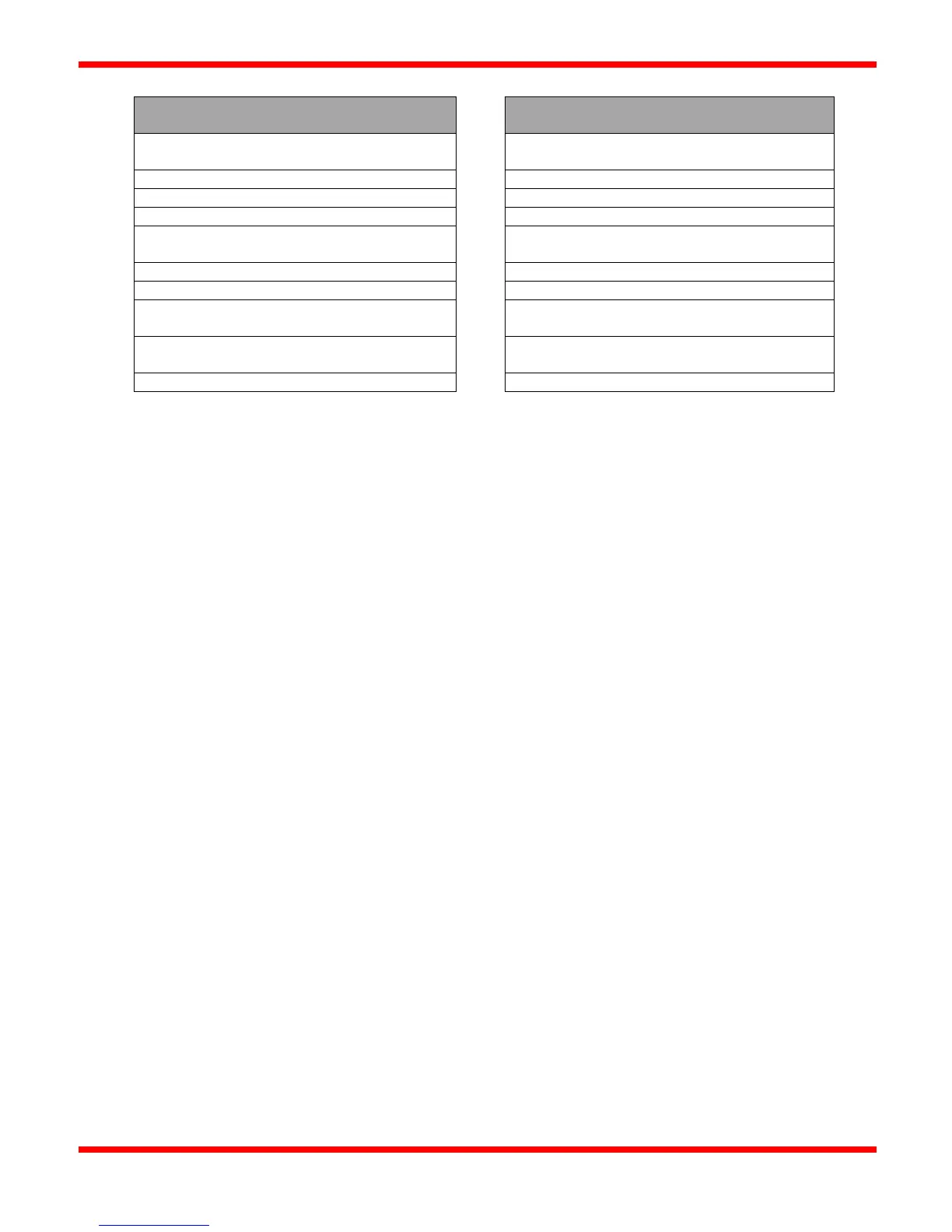
Minimum Required Wiring Connections
Optional or Additional Functionality Connections
Thermocouple 2 (Set TC2 menu option to
Disabled if not used)
Ignition Module: P, A, V, GND
Remote Start/Stop (jumper if not used)
Main Input Power (+12/24VDC, -12/24VDC)
High / Low Gas Shutdowns (jumper if not used)
Level Shutdown (jumper if not used)
Main Solenoid Output (if a minimum of two
valves are required)
Auxiliary 1 / 2 Shutdowns (jumper if not used)
Alarm Status (dry contacts)
Proof of Closure (jumper if not used)
Main Solenoid Output (keep open/unconnected if
not used)
T/Main Solenoid Output (keep open/unconnected
if not used)
Note: Ignition Module connections are matched with their corresponding Pilot/Main/TMain solenoid blocks. Ensure
that the solenoid outputs used (IGN1 / IGN2) match with the Ignition Module (IGN1 / IGN2).