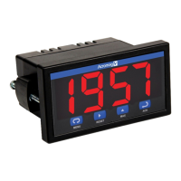
Vertu Series VPM3000 Process Meters & Temperature Transmitters
Instruction Manual
29
Display Functions and Messages
done
Selc
Select
Enter the Select menu
Func
Function
Select linear or square
Linr
Set meter for linear function
Sqrt
Square root
Set meter for square root
cutF
out
Output
Set meter for either relay
or analog output
(factory set only; only
included in certain models)
Aout
Analog output
Set meter for analog
rEly
Set meter for relay option
Aout
Analog output
Enable or disable analog
output
(factory set only; only
included in certain models)
Yes
no
Inty
ICal
Initial calibration
Enter initial calibration for
Curr
Calibrating current input
I lo
I low
Calibrate low current
I Hi
I high
Calibrate high current
volt
Calibrating voltage input
Vlo
V low
Calibrate low voltage
VHi
V high
Calibrate high voltage
diag
Diagnostics
Display parameter
led
CJC
CJC
Display cold junction
Cfg
CFG
Display meter
pts
Points
Display calibration points
RELY
Aout
Analog output
Display analog output
GoFF
Gain/offset
Display gain and offset
SErL
Serial
Display serial
Info
Information
Display software version
Offset Adjustment (Adj)
This parameter allows the user to select an offset
adjustment to the temperature being displayed. Offset
adjustment values can be either positive or negative
and can be any number within ±19.9°. The offset
adjustment value is programmed through the Adjust
menu.
The offset adjustment feature can be useful to
compensate for errors due to thermocouple junctions
or excessive lead wire resistance in RTDs.
The offset adjustment value is automatically reset to
zero whenever the type of temperature sensor is
changed (i.e. Thermocouple type or RTD curve).
Celsius/Fahrenheit conversion of the offset
adjustment value is automatic, see note 2 below for
important limitations.
Notes:
1. Offset adjustment is available only when TC or
RTD input is selected.
2. If adjustment value is greater than 11°C and the
temperature scale is changed to Fahrenheit, the
maximum applied adjustment will be 19.9°F.
Noise Filter (fltr)
Most applications do not require changing this
parameter. It is intended to help attain a steady
display with an unsteady (noisy) input signal.
The field selectable noise filter averages any minor or
quick changes in the input signal and displays the
reading with greater stability.
Increasing the filter value will help stabilize the
display, however this will reduce the display response
to changes on the input signal.
The filter level may be set anywhere from 2 to 199.
Setting filter value to zero disables filter function, and
bypass setting becomes irrelevant.
Noise Filter Bypass (byps)
The meter can be programmed to filter small input
changes, but allow larger input changes to be
displayed immediately, by setting the bypass value
accordingly.
If the input signal goes beyond the bypass value, it
will be displayed immediately with no averaging done
on it.
The noise filter bypass value may be set anywhere
from 0.2 to 99.9. It corresponds to percentage of full
scale for process inputs and to degrees Fahrenheit for
temperature inputs.
Increasing the bypass value may slow down the
display response to changes on the input signal.

 Loading...