Vertu Series VPM3000 Process Meters & Temperature Transmitters
Instruction Manual
7
Specifications
Except where noted all specifications apply to
operation at +25°C.
General
Display
4 digits (-1999 to 9999)
Display
Intensity
Eight user selectable levels. Default
intensity is 6.
NEMA 4X, IP65; panel gasket provided
Programming
Methods
Four front panel buttons, cloning with
Copy feature, PC with DisplayWizard
Noise Filter
Programmable from 2 to 199
(0 will disable filter)
Display
Process/RTD: 3.7-5/second
Thermocouple: 1.8-2.5/second
Overrange
Display flashes
9999
Underrange
Display flashes
-1999
Recalibration
All ranges are calibrated at the factory.
Recalibration is recommended at least
every 12 months.
Display
Stored until reset by user or meter is
turned off.
Password
Restricts modification of programmed
settings.
Non-Volatile
Memory
Settings stored for a minimum of 10
years.
Power
Options
85-265 VAC, 50/60 Hz; 90-265 VDC,
20 W max or
12-36 VDC; 12-24 VAC, 6 W max.
Required Fuse
UL Recognized, 5 A max, slow-blow;
up to 6 meters may share one fuse.
Normal Mode
Rejection
Isolation
4 kV input/output-to-power line; 500 V
input-to-output or output-to-24 VDC
supplies. VPM3121 model only: 100 V
Operating
Temperature
-40 to 65°C (-40 to 149°F)
Storage
Temperature
-40 to 85°C (-40 to 185°F)
0 to 90% non-condensing
Connections
Power & Signal: removable screw
terminal blocks accept 12 to 22 AWG.
Serial: RJ11 header, standard on all
Enclosure
1/8 DIN, high impact plastic, UL 94V-0,
color: Black
Tightening
Screw terminal connectors:
9.5 oz. (269 g) (including options)
UL File Number
E244293; UL 508 Industrial Control
Equipment
Warranty
3 years parts & labor. See Warranty In-
formation and Terms & Conditions on
www.acromag.com for complete details.
Process Input
0-20 mA, 4-20 mA, 1-5 V, ±10 V
Supply
Isolated, one or two transmitter sup-
plies P1: 24 VDC ±10% @ 200 mA
max (-10 option) P1 & P2: 24 VDC
±10% @ 200 mA & 40 mA max
(-20 option)
±0.05% FS ±1 count;
±0.1% FS ±2 counts for square root
Cutoff
0 to 9999 (0 disables cutoff function)
Point below at which display always
Scale without signal or calibrate with
signal source
User programmable over entire range
of meter
Impedance
Voltage range: greater than 1 MΩ,
Current range: 50-100 Ω, varies with
resettable fuse impedance
Protected by automatically resettable
fuse
(50 PPM/°C)
Voltage: ±0.02% FS
°
±0.80% FS
Voltage:
±0.06% FS
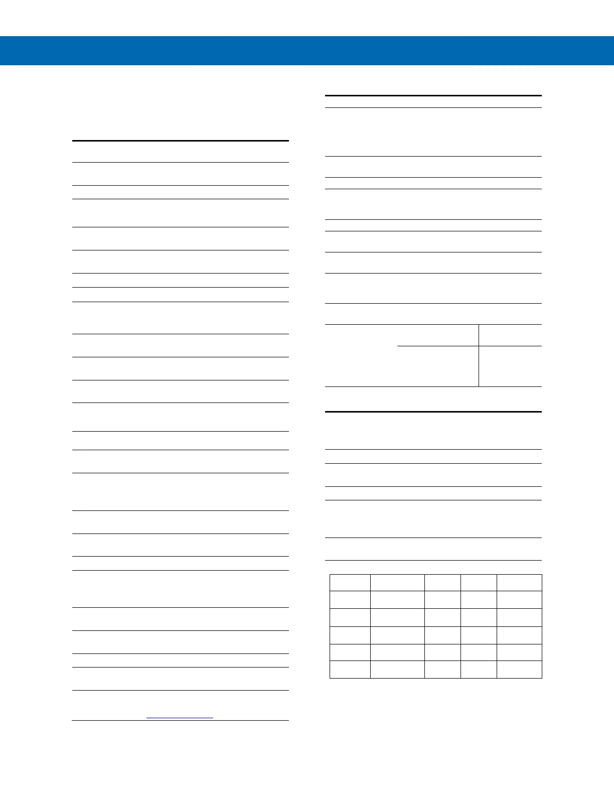
Temperature Inputs
Inputs
Factory calibrated, field selectable:
type J, K, T, or E thermocouples and
100 Ω platinum RTD (0.00385 or
Resolution 1°; type T TC & RTD: 1° or 0.1°
Cold Junction
Reference
Automatic
Offset
Adjustment
Programmable to ±19.9°. This parame-
ter allows the user to apply an offset
value to the temperature being
Input
Impedance
-58 to 1382°F
-50 to 750°C
±1°C
±3°C
-58 to 2300°F
-50 to 1260°C
-292 to 700°F
-180 to 371°C
-58 to 1700ºF
-50 to 927ºC
-328 to 1382°F
-200 to 750°C
 Loading...