Vertu Series VPM3000 Process Meters & Temperature Transmitters
Instruction Manual
38
Internal Calibration (ICal)
• There is no need to recalibrate the meter
when first received from the factory.
• The meter is factory calibrated prior to
shipment, for all input types, in milliamps,
volts, and degrees respectively. The
calibration equipment is certified to NIST
standards.
The internal calibration allows the user to scale the
meter without applying a signal. This menu is not
available if the meter is set up for TC or RTD inputs.
The use of calibrated signal sources is necessary to
perform the internal calibration of the meter.
Check calibration of the meter at least every
12 months. Each input type must be recalibrated
separately, if meter will be used with all input types.
• If meter is in operation and it is intended to accept
only one input type (e.g. 4-20 mA),
recalibration of other inputs is not necessary.
• Allow the meter to warm up for at least 30 minutes
before performing the internal calibration
procedure.
The Internal calibration menu is part of the Advanced
Features Menu.
1. Press the Right arrow and Menu button
simultaneously or hold the Menu button for
approximately 3 seconds to access the Advanced
Features Menu of the meter.
2. Press the Up arrow button to scroll to the Internal
calibration menu and press Enter/Ack.
3. The meter displays either current (Curr) or
voltage (volt), according to the meter input
setup. Press Enter/Ack to start the calibration
process.
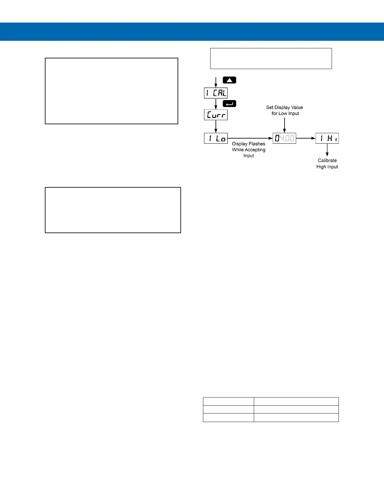
Example for current input internal calibration:
4. The meter displays Low input current (I lo).
Apply the low input signal and press Enter/Ack.
The display flashes for a moment while meter is
accepting the low input.
5. After the display stops flashing, a number is
displayed with the leftmost digit brighter than the
rest. The bright digit is the active digit that can be
changed by pressing the Up arrow button. Press
the Right arrow button to move to the next digit.
6. Set the display value to correspond to the input
signal being calibrated.
7. The display moves to the high input calibration
(I Hi). Apply the high input signal and press
Enter/Ack.
8. Set the display for the high input calibration in the
same way as it was set for the low input
calibration.
For instructions on how to program numeric
values see Setting Numeric Values, page 19.
The graphic above shows the calibration of the
current input. The voltage input is calibrated in a
similar way.
Tips:
• Low and high input signals can be any valid
values within the range of the meter.
• Observe minimum input span requirements
between input 1 and input 2.
• Low input must be less than high input
signal.
Error Message (E rr)
An error message indicates that the calibration or
scaling process was not successful.
After the error message is displayed, the meter re-
verts to input 1, allowing the appropriate input signals
to be applied.
The error message might be caused by any of the
following conditions:
1. Input signal is not connected to the proper
terminals, or it is connected backwards.
2. Wrong signal selection in Setup menu.
3. Minimum input span requirements not
maintained.
Minimum Input Span
The minimum input span is the minimum difference
between input 1 and input 2 signals required to complete
the calibration or scaling of the meter.
 Loading...