EasyManuals Logo

Acromag Vertu Series User Manual

Acromag Vertu Series
47 pages
To Next Page IconTo Next Page
To Previous Page IconTo Previous Page
Page #18 background imageLoading...
Page #18 background image
Vertu Series VPM3000 Process Meters & Temperature Transmitters
Instruction Manual
18
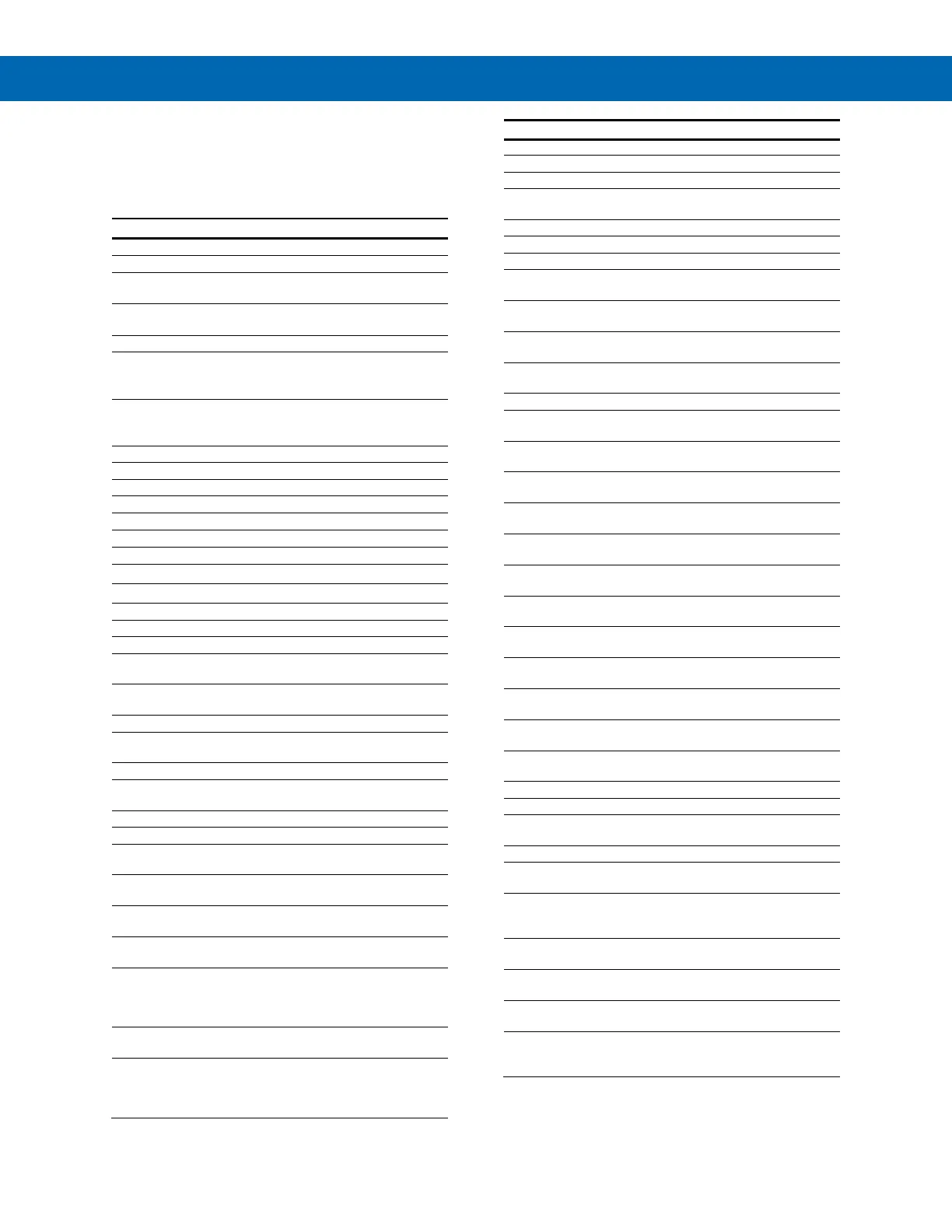
Display Functions and Messages
The meter displays various functions and messages
during setup/programming and operation. The
following table shows the displayed functions and
messages with their action/setting description.
Display
Parameter
Action/Setting
setu
Setup
Enter Setup menu
inpt
Input
Enter Input menu
4-20
4-20 mA
Set meter for 4-20 mA
input
0-10
0-10 VDC
Set meter for ±10 VDC
input
rtd
RTD
Set meter for RTD input
a385
Alpha 385
Set α = 0.00385
European curve 100
RTD
A392
Alpha 392
Set
α
= 0.00392
American curve 100
RTD
tC
TC
Set meter for TC input
0 J
0 J
Type J
1 k
1 K
Type K
2 T
2 T
Type T
3 t.0
3 T.0
Type T, 0.1° resolution
4 E
4 E
Type E
f C
°
F or
°
C
Set temperature scale
°
F
°
F
Set meter to Fahrenheit
°
C
°
C
Set meter to Celsius
dec.p
Decimal point
Set decimal point
prog
Program
Enter the Program menu
scal
Scale
Enter the Scale menu
Cal
Calibrate
Enter the Calibrate
menu
inp1
Input 1
Calibrate input 1 signal
or program input 1 value
dis1
Display 1
Program display 1 value
inp2
Input 2
Calibrate input 2 signal
or program input 2 value
dis2
Display 2
Program display 2 value
err
Error
Error, calibration not
successful, check signal
RELY
Relay
Enter the Relay menu
RLY1
Relay 1
Relay 1 setup
Act1
Action 1
Set relay 1 action
(automatic, latching, etc.)
Auto
Automatic
Set relay for automatic
reset
A-m
Auto-manual
Set relay for automatic +
manual reset any time
LtCH
Latching
Set relay for latching
operation
L-CL
Latching-
cleared
Set relay for latching
operation with manual
reset only after alarm
condition has cleared
Altr
Alternate
Set relays for pump
alternation control
oFF
Off
Disable relay and front
panel status LEDs
Disable relay’s fail-safe
operation
Display
Parameter
Action/Setting
Set1
Set 1
Program set point 1
rSt1
Reset 1
Program reset point 1
RLY2
Relay 2
Setup relay 2
Act2
Action 2
Set relay 2 action
(automatic, latching, etc.)
Set2
Set 2
Program set point 2
RSt2
Reset 2
Program reset point 2
FLSF
Fail-safe
Enter Fail-safe menu
FLS1
Fail-safe1
Set relay 1 fail-safe
operation
on
On
Enable fail-safe
operation
off
Off
Disable fail-safe
operation
FLS2
Fail-safe2
Set relay 2 fail-safe
operation
DLAY
Delay
Enter Time Delay menu
DLY1
Delay 1
Enter relay 1 time delay
setup
On1
On 1
Set relay 1 On time
delay
OFF1
Off 1
Set relay 1 Off time
delay
DLY2
Delay 2
Enter relay 2 time delay
setup
On2
On 2
Set relay 2 On time
delay
OFF2
Off 2
Set relay 2 Off time
delay
brek
Break
Set RTD/TC input break
relay behavior
Brk1
Relay 1 Break
Set relay 1 input break
relay behavior
Off
Off
Set relay to non-alarm
condition at break
On
On
Set relay to alarm
condition at break
Brk2
Relay 2 Break
Set relay 2 input break
relay behavior
Aout
Analog output
Enter the Analog output
menu
Scal
Scale
Enter the Scale menu
Dis1
Display 1
Program display 1 value
out1
Output 1
Program output 1 value
(e.g. 4 mA)
Dis2
Display 2
Program display 2 value
out2
Output 2
Program output 2 value
(e.g. 20 mA)
SEbr
Sensor break
Program TC or RTD
sensor break value for
analog out
pass
Password
Enter the Password
menu
unlC
Unlocked
Program password to
lock meter
loCd
Locked
Enter password to
unlock meter
9999
-1999
open
Flashing
display
Overrange condition
Underrange condition
Open TC or RTD sensor

Table of Contents

Questions and Answers:

Question and Answer IconNeed help?

Do you have a question about the Acromag Vertu Series and is the answer not in the manual?

Acromag Vertu Series Specifications

General IconGeneral
BrandAcromag
ModelVertu Series
CategoryMeasuring Instruments
LanguageEnglish