5A 250VAC
5A 30VDC
1A 250VAC
1A 30VDC
0V
DOOR
CONTACT
PUSH
BUTTON
AUX
INPUT
RELAY 1
N/C N/OC
OP2
OP3
SENSE
CLOCK
DATA
RED
GREEN
B 0V
TX
RX
NETWORK 1
1A 250VAC
1A 30VDC
+
DOORS
A
B
0V
SERIAL/PRINTER
0V
+12V
0V
SENSE
CLOCK
DATA
RED
GREEN
READER 2
+12V
0V
OUTPUTS 1
0V
DOOR
CONTACT
PUSH
BUTTON
AUX
INPUT
OP2
OP3
MAINS
PRESENT
AUX RLY 1
N/C N/OC
RELAY 2
N/C N/OC
AUX RLY 2
N/C N/OC
5A 250VAC
5A 30VDC
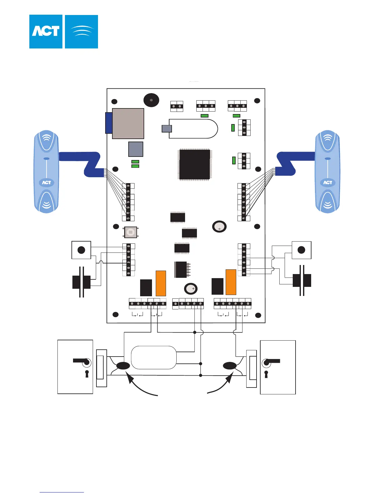
This illustration shows wiring for
normally energised locks.
If normally de-energised locks
are required, use the N/O relay contacts.
Note:
If the Mains Present or Door
Contact inputs are not used,
they should be linked to 0V
Door 2 Contact
Release Button
Door 1
Release Button
Door 2
Door 1 Contact
Card / Proximity or Pin
Reader - Door 2
Card / Proximity or Pin
Reader - Door 1
Important!
Always Place Varistor
Across Lock Terminals
Door 2
Door 1
12V DC
Power Supply
12V
0V
31
Typical ACTpro 4000 Configuration
(Standalone)
Cable: 8 Core Screened
Belden 9504 or equiv
Max length 100 Meters
Cable: 8 Core Screened
Belden 9504 or equiv
Max Length 100 Meters
T
B 0V
NETWORK 2
A A
LINK
SPEED
+12V 0V
INPUTS 1
OUTPUTS 2
INPUTS 2
ENTRY/EXIT
READER 1
ENTRY/EXIT
+5V 0V
+12V 0V