OP1
TAMPER
MAINS
PRESENT
+
12V DC
-
NC
C
OP2
NO
NC
C
NO
SENSE
0V
RED
GREEN
+5V
CLOCK
DATA
5A 250VAC
5A 30VDC
5A 250VAC
5A 30VDC
1 2 3 4 5 6 7 8
N ADDRESS
On
OP3 OP4 0V IP1 IP2 IP3
DTR RX TX 0V B A
SERIAL NETWORK
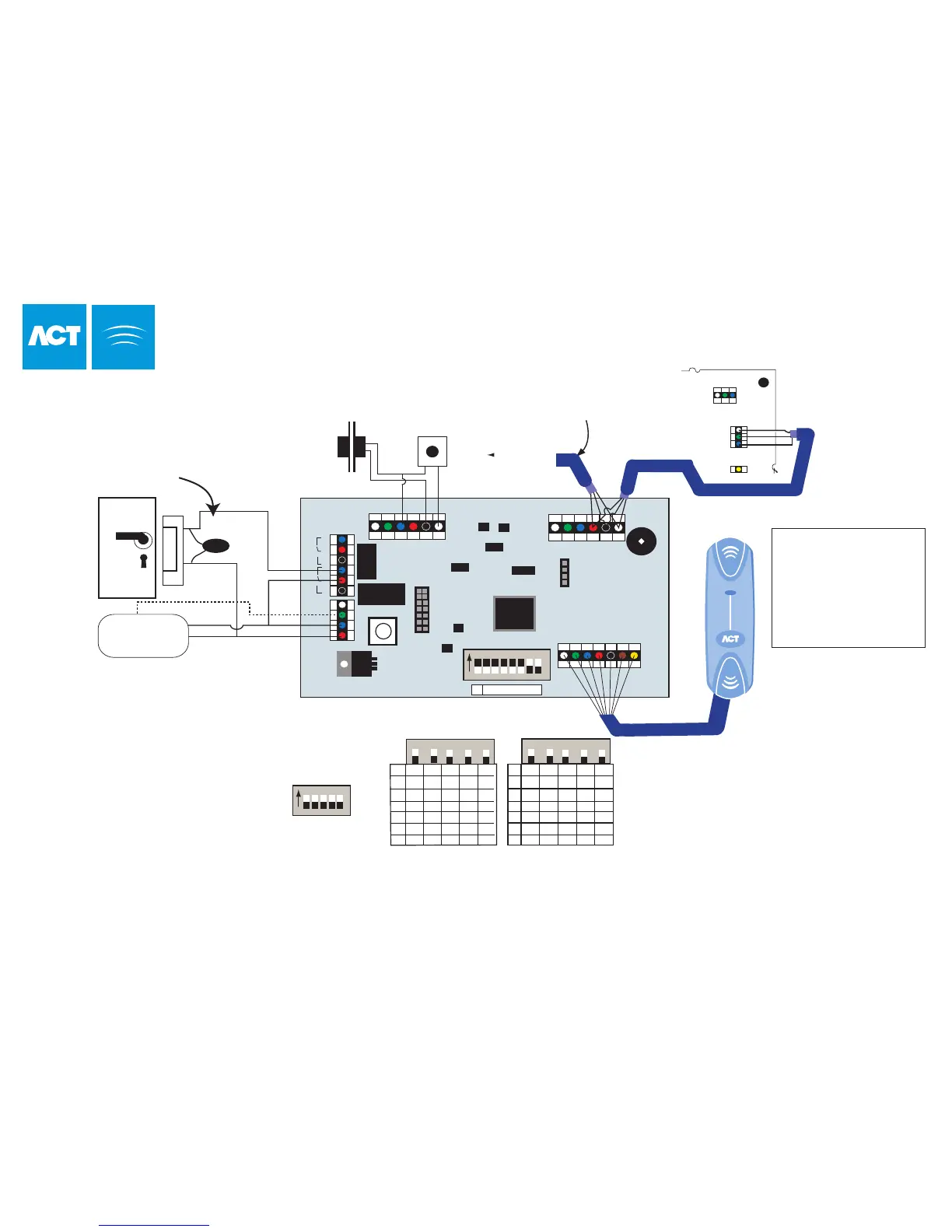
To set the door number,
set address switches
4-8 as shown
NETWORK 1
Important !
Always Place Varistor
Across Lock Terminals
Door
Release
Button
B
A
Shield
FACTORY DEFAULT
This unit should be reset to its
factory default condition before
installation. To do this, power
the unit up with ALL switches in
the OFF position. The two LED's
will illuminate for about 2 sec.
The correct switch settings may
then be set.
Door
Contact
Entry/Exit Reader
ACTpro 4000
Note:
If the Mains Present or Door
Contact inputs are not used,
they should be linked to 0V
This illustration shows wiring
for a normally energised
lock. If a normally de-energised
lock is required, use the
N/O relay contacts.
Entry Reader
A
B
0V
CTS
4 5 6 7 8
On
03 OFF OFF OFF ON ON
04 OFF OFF ON OFF OFF
05 OFF OFF ON OFF ON
06 OFF OFF ON ON OFF
07 OFF OFF ON ON ON
08 OFF ON OFF OFF OFF
09 OFF ON OFF OFF ON
10 OFF ON OFF ON OFF
11 OFF ON OFF ON ON
12 OFF ON ON OFF OFF
13 OFF ON ON OFF ON
14 OFF ON ON ON OFF
15 OFF ON ON ON ON
16 ON OFF OFF OFF OFF
Power
Supply Unit
+12V
0V
Max 30M
Total Length max 1.4km
For Clock & Data Readers,
wire exit reader in parallel
but leave it's sense line
unconnected.
For Wiegand Readers, wire
the DATA 0 of the exit reader
to SENSE on the ACTpro
100
Network cable use either:
(1)Single shielded twisted pair, Belden 9501 or similar.
(2)CAT5 Cable: A/B must use the same twisted pair.
To next door
White
Green
Blue
Red
Black
Brown
Yellow
Orange
SENSE
CLOCK / DATA 1
DATA / DATA 0
+5v
0v
RED
GREEN
(Buzzer Ctrl)
Wiring for Clock and Data / Wiegand Reader
DOORS
4
5
6
7
8
4
5
6
7
8
Required
Address
Required
Address
ACTpro 100 Door Station Installation
Cable: 8 Core Screened
Belden 9504 or equiv
OP1 = Main Relay
OP2 = Aux Relay
OP3 = OP3
OP4 = OP2
IP1 = Aux Input
IP2 = Door Contact
IP3 = Push Button
LED Functionality:
Red LED indicates the status of communications with the Controller.
While online to the controller the Red LED will flash rapidly.
If there is a problem it will flash slowly (about once a second).
Green LED will flash if an event occurs on the ACTpro 100
32
A B 0V