Card / Proximity or Pin
Reader (Entry)
Card or Proximity
Reader (Exit)
Controller
SENSE
CLOCK
DATA
+12V
0V
RED
GREEN
Card/Prox Reader
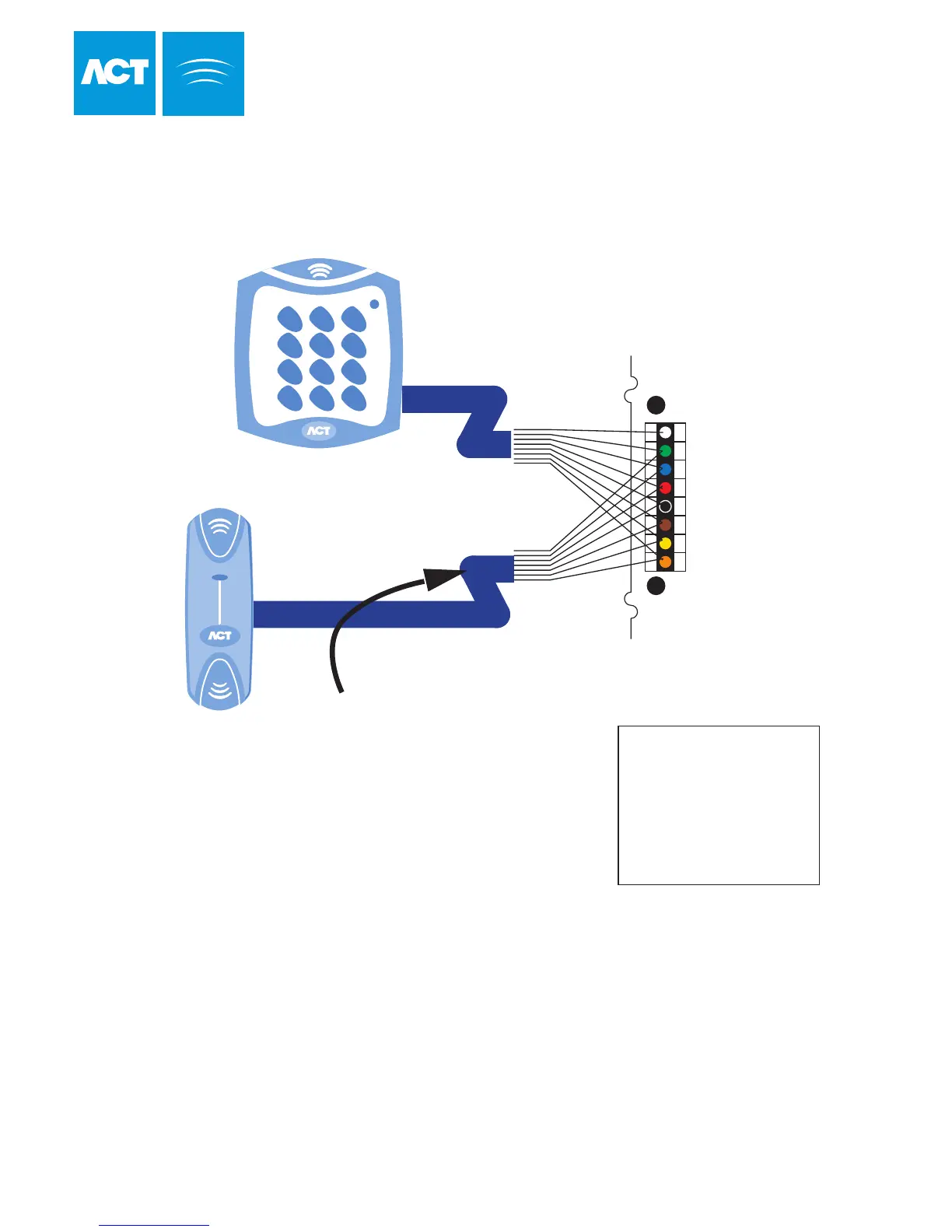
For Wiegand Exit readers
Connect DATA 0 of the exit reader
to SENSE on the controller. Leave
SENSE on the readers unconnected.
Wire both readers in parallel but leave
the SENSE line on the Exit reader unconnected.
The above diagram is valid only
for clock-and-data type readers.
White
Green
Blue
Red
Black
Brown
Yellow
Orange
SENSE
CLOCK (DATA 1)
DATA (DATA 0)
+12V
0V
RED
GREEN
(Buzzer Control)
Wiring for Clock and Data / Wiegand Reader
The standard wiring colours for
ACTpro Proximity and Pin readers
is shown above. Readers
may be a maximum of 100m
from the controller when powered
from +12V.
33
Wiring for Entry/Exit Readers
Cable: 8 Core Screened
Belden 9504 or equivalent
Max length 100 Meters