200S 57
II - 4 I/O Connections
Wiring the Serial communication cable
The wiring of the serial communication cable depends on the device
being connected (see technical documentation for external device)
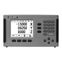
Pin assignment
Signal
Pin layout of RS-232-C / V.24 data interface.
Pin connection for serial port with handshaking.
Pin Assignment Function
1 No assignment
3 TXD - Transmitted Data
2 RXD - Received data
7 RTS - Request to send
8 CTS - Clear to send
6 DSR - Data set ready
5 SIGNAL GND - Signal ground
4 DTR - Data terminal ready
9 No assignment
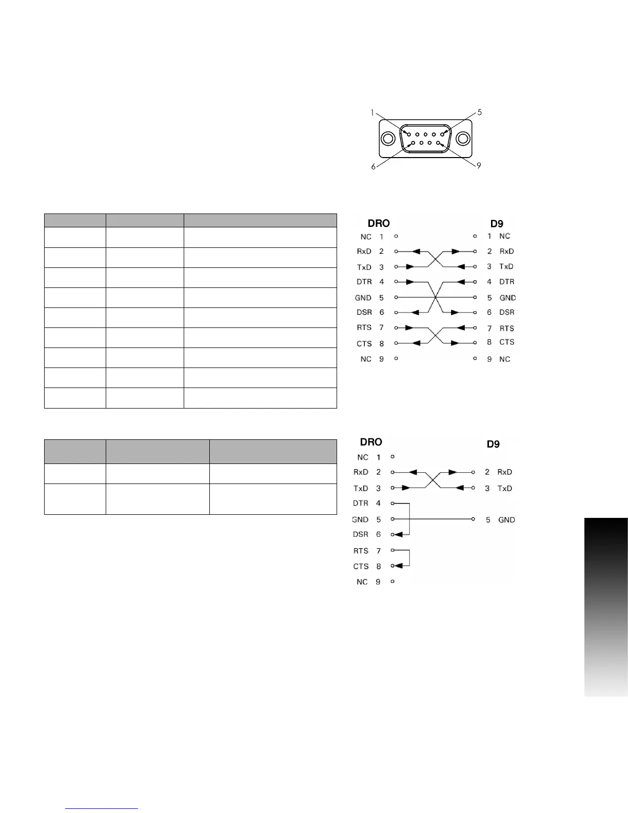
Pin connection for serial port without handshaking.
Signal Signal Level
“1” = “active”
Signal level
“0” = “inactive”
TXD, RXD -3 V to - 15 V +3 V to + 15 V
RTS, CTS
DSR, DTR
+3 V to + 15 V -3 V to - 15 V
 Loading...